When you click on links to various merchants on this site and make a purchase, this can result in this site earning a commission. Affiliate programs and affiliations include, but are not limited to, the eBay Partner Network.
I think I succeeded to fix the sensor. Here is the situation after destroying the sensor:
I learned, that the condition of the sensor can be measured by measuring the resistance over it. So I measured the resistance of the other (still in good shape) sensor:
After that, I dig out internals of the sensor with a nail. Little hammering and it came out quite neatly:
Had to drill a bit to see some copper:
I pushed the internals and the cap together and measured the resistance. It worked!
Now the glue is drying. I still have to wait for the new shocks before starting the re-assemble. I really wonder why these sensors are so expensive as the internals are pretty simple, just a magnet and a copper spool.
The sensor is a inductor that will read as a fundamental reading of 1300 ohms ( same as the crankshaft position sensor ) from the ABS module up front . A functional test is to spin the tire in the correct direction and will read on the AC scale around 1.0 volts
The car must go at least 12.5 MPH before the dash light extinguishes
The 4 sensor wire pairs are marked as different colors
As previously pointed out the rear sensor to suit many Audi"s around the early 2000's will fit. They are readily available & not expensive.
I recently purchased 2 of them locally at a very keen price, albeit they are made in China.
The only problems are -
# Sensor body fitting into the hub is too long.
# lead is orientated in the wrong direction, will go straight into the backing plate on brake assembly.
Both these issues where resolved by fabricating the space/mount shown in the attached file. Note left & right mounts need to be unique to the respective side.
Thanks for the helping info. A couple of questions about this Audi sensor: did you install the audi sensor to the metal shell of the original sensor, or did you remove the original sensor totally before installing the audi sensor? About the orientation: was it 90 degrees from the original (I was not 100% sure from the photo)? And if so, should the wire go to the same direction as for the original sensor after this re-assembly of the audi sensor? How thick was the spacer used below the Audi sensor? Sorry for the amount of questions, but as always, the devil is in the details.
With the 1994 year of your car is it a X300 or a X40 model ?
The shell of the previous sensor should be removed
You can just sit the sensor in place and spin by hand the wheel in the correct direction and watch for the 1.0 volts AC
Then you can spin the sensor 180 degrees if not working , Heavy tape may be a temporary securement at this stage
The term working would be a car on the ground driving above the 12.5 MPH if the ABS light " latched " on , In your case I don't think you ever got the light
The spacer would have to be high enough or the sensor will probably hit the reluctor ring that spins and destroy the sensor
Hi again. I thought I managed to repair the destroyed sensor. When measuring during driving the AC voltage, it was around the mentioned 1V and seemed to change according to the speed (higher speed, higher voltage). I measured also the other side, which should be ok, and the result was more or less the same. So I started to be positive. Anyhow, she “Anti lock signal” remained visible and the speed showed 0 all the time.
Next I assumed a connection error, so I cut the wires and joined them visibly to be sure about the connection. It did not help.
A funny thing was, that during a test drive, the speedometer worked for a while, but then died again.
I have now done several test drives. I have also connected the measurement on-line, so I can see the AC voltage from the sensor while driving. The connection is steady, the voltage is there all the time and varies according to the speed, but the speedometer works only occasionally. Sometimes it works quite a long time ok, but then disappears even the voltage continues showing like earlier. The best it works when starting the driving from a cold condition, but that is not a rule that you can trust. It just mostly works better in the beginning of the drive. I have not found a clear logic why the measurement comes and goes like it does
I just have a basic measurement with voltage, amperes and ohms. I do not have a frequency measurement. Could the main message to the speedometer be the frequency of the AC current? It could be logical. If so, what could be the reason for the unsteady frequency of the current from the sensor? I had to make some violence to the sensor while repairing it and it would not be a wonder, if I had damaged something, but the basic structure of the sensor (a magnet surrounded by a spool) is quite simple.
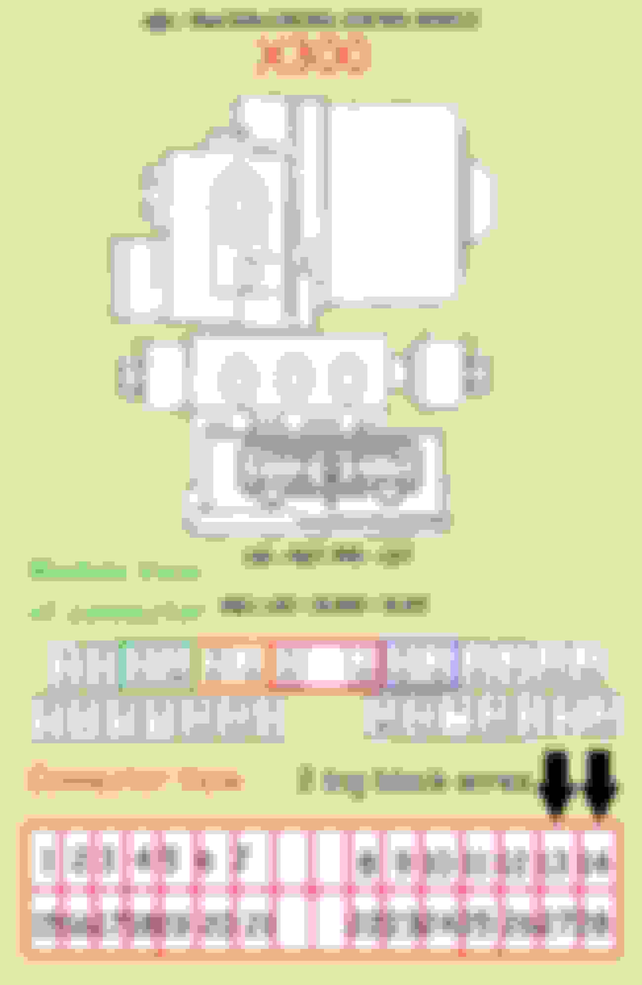
The ABS module has a speed output with the Green / Pink wire after receiving it from the left rear sensor , is this a corrupted signal on the Greeen /Pink wire ?
See page 72 of a 1997 model , 1994.5 should be the same
This Green / Pink wire inputs into the instrument cluster as the speedometer
see page 96
The left wheel sensor also triggers the variable steering module if equipped
This module is located next to the 2 front windsheld heat relays if equipped
See page 19 of the LWB doc below
The wheel speed for this function comes out of the instrument cluster ( speedometer ) as the blue wire , is it a pass through signal that can be corrupted ?
Cruise control module pin FC17 - 6
Same blue wire signal comes out from the instrument cluster
I was able to unplug the variable steering module. I also found the cruise control module and could even reach it somehow, but was unable to unplug the connector. I tried all possible ways from that position, but without any success. As I could not properly see the module, most probably I just could not figure out how this connector could be opened. Any advice?
I concur with @Stu Jags , I too used the Audi sensor sourced from a box containing 100's used Audi sensors at my friends European auto repair shop. After a few minutes of digging, I found something that was close, asked him what car did this come off of and he responded "an Audi A4". Further researched discovered it was widely available; $15-$40. You'll need to space it up a bit and swap out the connector under rear seat but works fine and easily sourced.
QUOTE=xalty;2291633]Dropped my diff and discovered somebody was in there already, PO was a jag tech. 300 sensor in a 308 hub?
If you used a 308 sensor could it be used with out a spacer and just use to spades and sealant
QUOTE=xalty;2291633]Dropped my diff and discovered somebody was in there already, PO was a jag tech. 300 sensor in a 308 hub?
If you used a 308 sensor could it be used with out a spacer and just use to spades and sealant
[/QUOTE]
Well since you drug up an old post (and oddly enough I am about to deal with an ABS sensor issue) I am about to dive into my sensors again (after a 4 year "no issues" vacation) So the 2 biggest things you'll have to deal with other than physical fitment are going to be
#1, gap distance from the sensor to the reluctor/tone ring. To close... well that means a damaged sensor. To far away and you'll have to deal with a late/no/weak sensor output signal
#2, polarity... Electronics that rely on an analog signal and convert it to a usable signal (processed) use 1 of 3 methods. They are, "rising" or "falling" or "0" voltage crossover point for timing purposes. In some circumstances this may not be an issue. So for sanity sake, I would hold off sealing the connection until you confirm which of the first 2 it may require. In the case of the 3rd (zero voltage crossing point) then it likely will not matter.
To better define this, look up a sine wave signal. "Rising" is the up slope going into the sine wave and "Falling" in the down slope.
Last edited by Darren_M; Mar 26, 2024 at 05:50 PM.
Hi. I used Audi A4 sensor, so unfortunately I do not know how 308 sensor would fit. Sorry.
QUOTE=John1970;2734972]QUOTE=xalty;2291633]Dropped my diff and discovered somebody was in there already, PO was a jag tech. 300 sensor in a 308 hub?
If you used a 308 sensor could it be used with out a spacer and just use to spades and sealant
There was some discussion earlier of a X308 senser on a X300 and if I recall the sensor has to be spun 180 degrees on the hole which leaves the question of the mounting bolt ear
The late model X 300 , X300 sensor left will not work on a right and vice versa.
The early X300 sensors have a different part # then the later X300s