When you click on links to various merchants on this site and make a purchase, this can result in this site earning a commission. Affiliate programs and affiliations include, but are not limited to, the eBay Partner Network.
Hi all together,
right now I'm upgrading my XJR with a generation V Eaton supercharger, the uprated Bosch 0392022010 intercooler pump and a few other small things. What already bothered me the last time (2 years ago) when changing the knock sensors was, that I didn't had and find any information about the vacuum lines (e.g. diagram, flowchart).
For example: the JEPC and jaguarclassicparts picture shows two vac lines (part 13+15) and a t-piece which are attached to the fuel rail. But my car does not have two vac lines nor the t-piece. It does only have one vacuum line which connects the valve at the fuel rail to the supercharger outlet duct.
Second example: the JEPC and jaguarclassicparts view offers quite a number of different vac lines and t-pieces which are supposed to be fitted to my car (VIN>F20645). But there aren't that much vac lines in my engine bay.
Already back then I determined having a very small air leak somewhere before the supercharger. Since the STFT of both banks behave the same way and show the same swings, the air leak is not determined to one bank. The STFTs are striking a little bit when the engine is running at low RPM. The higher the RPM, the STFT will return to normal condition. And since I do not have any codes (except of P0420, P0430 when finishing the drive cycle while going 60 mph constantly for a while), no performance and/or MOT issues, the air leak is supposed to be quite tiny.
Because I renewed all the gaskets, seals and O-rings of the air intake system (supercharger gaskets, throttle body and elbow gaskets, bypass-valve O-rings etc etc) already back then, I'm quite sure the air leak isn't caused there.
So right now, I'm quite curious if there's something wrong with the vac lines. I already examined the lines, connectors and t-pieces and found them in an excellent condition.
Just to be clear: If I can get rid of the air leak, it will be a nice-to-have, but no must. In the first place, I want to understand how the vac lines run and how they interconnect so that I can be sure that the preowner didn't mess them up.
Does anybody know a manual, a diagram or anything else which sheds light on that mystery?
Thanks very much! Alexander
Last edited by xjr2014_de; Feb 14, 2017 at 04:37 AM.
Reason: typo
Do you have the X308 Workshop manual? This is provided by jimlombardi for download.... https://www.dropbox.com/s/vujkjrxklu...anual.pdf?dl=0
I believe starting on page 1114 will get you in the right direction for the connections. Though I do not see an overall diagram of the vacuum routing (it may be listed elsewhere), it shows close up specifics. Like from the SC Outlet duct, going under the intercooler for example on page 1132.
Hello Highhorse,
thanks for chiming in!
Yes, I already noticed the section "Intake Air Distribution" in the manual, but it doesn't make clear how the vacuum lines interconnect. There are a lot of hints hidden in the running text in the section "Intake Air Distribution and Filtering - Supercharged Vehicles". On the other hand, the manual mixes up AJ26 engine features with AJ27 engine features in many cases. So the section mentioned above says:
The inlet vacuum feed for the fuel rail pressure regulator and the cruise control system is taken from the supercharger outlet duct. The feed pipe is located below the large charge air cooler coolant filler plug.
But that's wrong since the cruise control system for AJ27 engines is controlled fully electronically. So I always remain sceptical when reading which information is meant for the AJ26 and which for the AJ27.
When the AJ27 was introduced, a lot of features which were vacuum controlled before had been replaced with electronic controls.
Does anybody tackled the same considerations as me when working on the vac lines and made a drawing or picture of his vac line configuration?
It sounds a bit simple, but does your car have the vehicle emissions control label? On mine, the label is towards the left of the car, on the plastic panel that is under the hood, right above the radiators. That has the vacuum routing diagram on it. Not sure if the AJ27 ones keep with that.
Also, post updates of setting up the GenV blower. I have one in my basement waiting on rear needle bearings and warmer days. I know the 4.0 intake elbow needs to be machined a bit to clear the rear bearing caps that stick past the blower intake face, it would be good to see a picture of that done, even though the principle seems pretty simple.
Last edited by nilanium; Feb 14, 2017 at 10:58 AM.
Thanks for the useful hint. I'll check this tomorrow evening however I don't remember any label like the one you mentioned on the radiator panel.
I know the 4.0 intake elbow needs to be machined a bit to clear the rear bearing caps that stick past the blower intake face, it would be good to see a picture of that done, even though the principle seems pretty simple.
Well, that's new to me. I do know (and noticed it, when held in hand) that the rear bearings protrude a little bit. But from what I read here, I thought I'd have to either customize the regular gasket (used in the 4.0 SC engines, NCC7754BA) OR just use the appropriate gasket from the 4.2 SC engines (AJ83292). So I got the 4.2 gasket, which is a bit thicker than the 4.0 gasket and was hoping this will compensate the offset. I don't recall where I read it, but I think it stated there that it will be just plug'n'play with the new style gasket without modifying anything. I'll keep you updated :-)
For the decals on the radiator plastic trim cover, you can get them from Welsh Ent.
Emmissions decal-NXD4744BA $5
Vacuum Routing decal-NNF4744GA $7
...at minimum, you can look at them on their site and see what you need for the connections.
@Highhorse:
This is absolutely staggering! Thank you very much! Until nilanium's input and your's as well I never expected the routing diagram printed on a decal in the engine bay but in none of my numerous Jag documentations.
Even though the JEPC and jaguarclassicparts view is quite confusing and not matching the sight in my engine bay, the decal definitely shows my configuration. So, let's call it a day and declare the mystery as solved :-)
As the decal picture on Welsh Ent.'s website is copyright protected, here's the photoshopped, copyright free version ;-)
Also, post updates of setting up the GenV blower. I have one in my basement waiting on rear needle bearings and warmer days. I know the 4.0 intake elbow needs to be machined a bit to clear the rear bearing caps that stick past the blower intake face, it would be good to see a picture of that done, even though the principle seems pretty simple.
As promised: No machining needed as long as you get the gasket from the 4.2 l engines (AJ83292). Its metal core is entirely wrapped with black rubber, so the sealing quality might be way better than of the old style gasket, which has just a tiny rubber ring around the port.
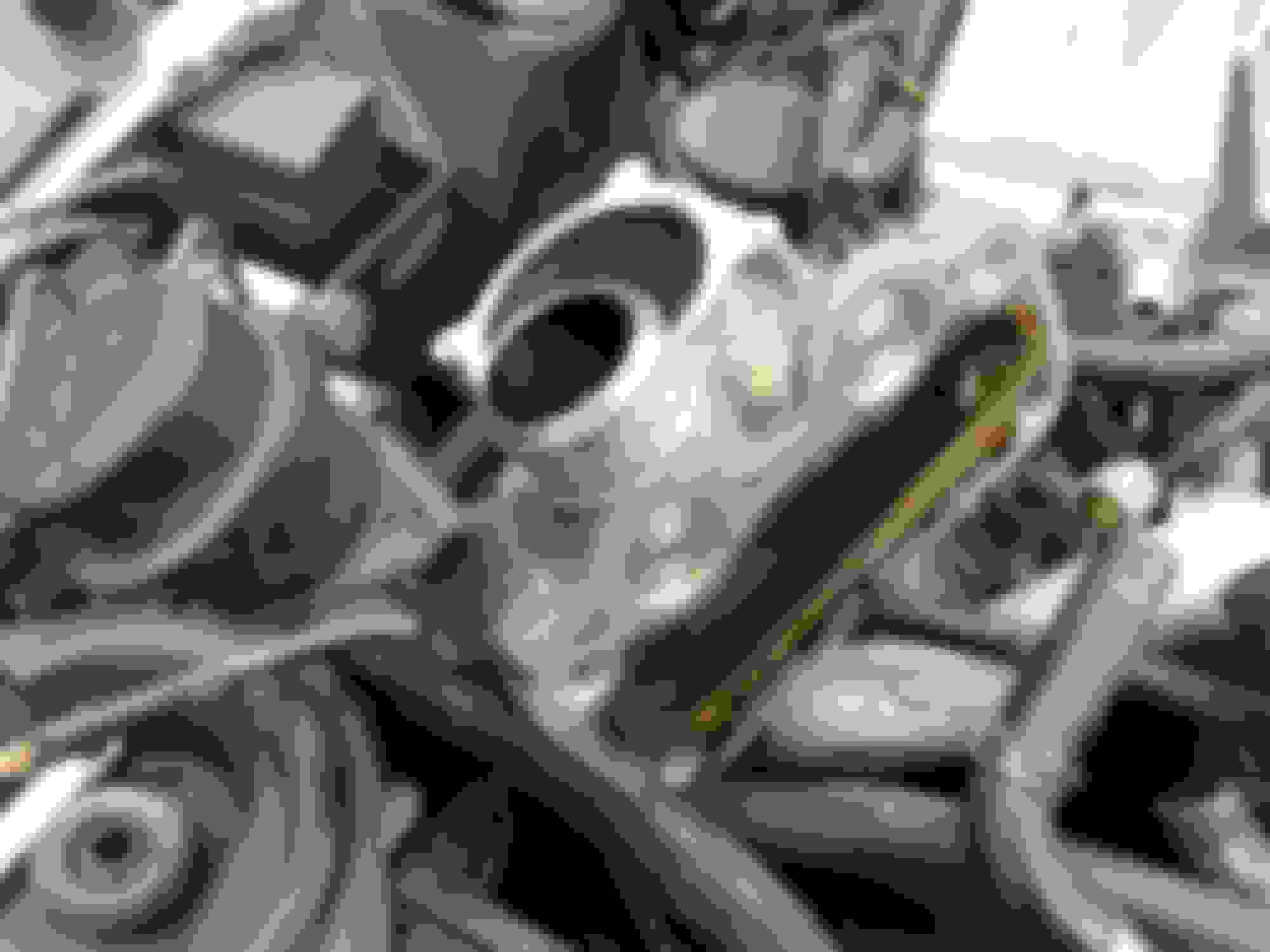
I took some pictures, as I assembled the GenV supercharger with the intake elbow on trial. It's hard to imagine, how the intake elbow needs to be machined, so that the GenV supercharger fits...since the old style gasket has to be machined too...
As the new style gasket is thicker, I might face trouble when attaching the intake elbow to its bracket (see picture). As the supercharger remains on the same position on the engine, the thicker gasket pushes the intake elbow a few millimeters backwards, so that there might be an offset with the bolt holes of the bracket. But doesn't look like much of a problem.
All very good to know! I guess as long as the bearing caps aren't bottoming out against the elbow face then there's no machining needed. I'm glad I got the elbow gasket along with the supercharger when I got it. I'm much more comfortable reaming out mounting bolt holes a few mm back (if needed) than I am machining my intake elbow face
It's too bad the 4.2 intake elbow wouldn't work with the 4.0 setup easily, the bypass valve/routing looked to be setup a bit differently. Here's a picture of the 4.2 elbow face from the car I pulled mine from.
It looks like it has pinholes aligned with the pinholes in the blower bearing caps, maybe for venting purposes?