Heater Valve Vacuum source
#1
I have begun a major service on my '90 Majestic, one of the models lacking a heater valve, AND,
my car doesn't have one. To be sure the A/C in my Majestic has always been marginal at best and useless in Florida summers.
I have two heater valves (factory and A/M plastic poppet) and the hoses to install and I have two questions:
1. Can anyone suggest a good vacuum source for correctly, timed operation?
2. What is the location of the vacuum tank?
I found the source of my oil leak - the oil fill tube mount/seal. Crankcase ventilation blocked,
pressurizing the crankcase and forcing oil out? I have a severe mess to clean up and repair.
I found THE source of my FF44 failure; all of the intake manifold screws were loose! No doubt due to a tech under pressure
from flat rate. My car had a head gasket change at some point before my ownership...
Thanks,
Roger
Last edited by Roger95; 11-04-2020 at 04:22 PM. Reason: Rephrase wuestion
#2
The non-heater control valve cars still received the vacuum solenoid and wiring from the factory, they just capped the outlet. You can run vacuum hose or rigid line through the firewall and to the new control valve.
I canít remember exactly which solenoid is the heater control valve one, but itís there behind the dash. IIRC, the various XJ40 Model Year Updates describe it. The Delanair MKIV climate control guide also mention it too.
Nick
I canít remember exactly which solenoid is the heater control valve one, but itís there behind the dash. IIRC, the various XJ40 Model Year Updates describe it. The Delanair MKIV climate control guide also mention it too.
Nick
#3
The solenoid is located on the left side of the trans tunnel behind a plastic cover.(under the radio)
The vacuum is ALREADY attached.
I always run a hard red plastic line from the vacuum solenoid to the heater valve. (like the 3.6 and 93-94MY sedans)
The original solenoid location will be the one most rearward of the two on the left side.
The vacuum is ALREADY attached.
I always run a hard red plastic line from the vacuum solenoid to the heater valve. (like the 3.6 and 93-94MY sedans)
The original solenoid location will be the one most rearward of the two on the left side.
#5
#6
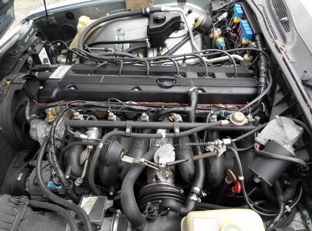
The crankcase vent valve is the black valve top dead center of the intake manifold.
The two fittings with hoses in the rear of it are coolant, the single fitting with hose in the front
is the crankcase vent and the one to clean. Pull the hose off the fitting and clean it out with brake cleaner, q tips
and a pick if it is plugged. From today forward I'll swab it out with every oil change.
Last edited by Roger95; 11-06-2020 at 07:36 PM.
#7
Join Date: Feb 2014
Location: Crossroads of America
Posts: 19,415
Received 12,767 Likes
on
6,395 Posts
Regarding your intake manifold screws and nuts, looseness is very common. The torque specification is 16 to 20 lb/ft, but that thick plastic-core gasket with paper on both sides seems to compress over time, leaving the screws and nuts loose. On our '93, I finally made checking those screws part of my oil change maintenance checks, along with cleaning the goop out of the air intake, cleaning the grounds in the engine bay, especially the ones referenced by the ECM (the two on the intake manifold and the one on the firewall behind the cylinder head), cleaning the MAF sensor and its connector, cleaning the TPS electrical connector, etc.
Cheers,
Don
Last edited by Don B; 11-07-2020 at 10:56 PM.
The following users liked this post:
impster (11-07-2020)
Trending Topics
#8
Thank you Don! This is all work that should have been done in the past, but I haven't been able to take the car off the road for the length
of time I need until now. I have one quandary remaining; I bought a new TPS some years back and I'm considering installing it. The original has 113+K miles
and has been trouble free, though it is thirty years old. Do I install the new, or "let that sleeping dog lie" until it gives me trouble (my inclination)? I have broken loose the mounting screws and never siezed them so removal and install in the future will be fairly easy. I have a NEW starter to install, which I'll accomplish in the next day or so.
Breaking loose the upper screw is always a PIA. I've done two in the past, one from under with an air gun and assistant and one from above with heat and bad words.
Do you have any suggestions on a wrench so I can avoid the heat and bad words?
Thanks, Roger
#9
The crankcase vent valve is the black valve top dead center of the intake manifold.
The two fittings with hoses in the rear of it are coolant, the single fitting with hose in the front
is the crankcase vent and the one to clean. Pull the hose off the fitting and clean it out with brake cleaner, q tips
and a pick if it is plugged. From today forward I'll swab it out with every oil change.
The two fittings with hoses in the rear of it are coolant, the single fitting with hose in the front
is the crankcase vent and the one to clean. Pull the hose off the fitting and clean it out with brake cleaner, q tips
and a pick if it is plugged. From today forward I'll swab it out with every oil change.
I thought for a while that you were talking about the Idle Control Valve but when you mentioned two coolant hoses you lost me.
My car is a 94 and I know the configuration is different, but surely not THAT different!.
Larry
#11
#12
The following users liked this post:
Don B (11-09-2020)
#13
Join Date: Feb 2014
Location: Crossroads of America
Posts: 19,415
Received 12,767 Likes
on
6,395 Posts
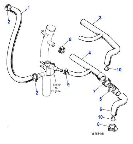
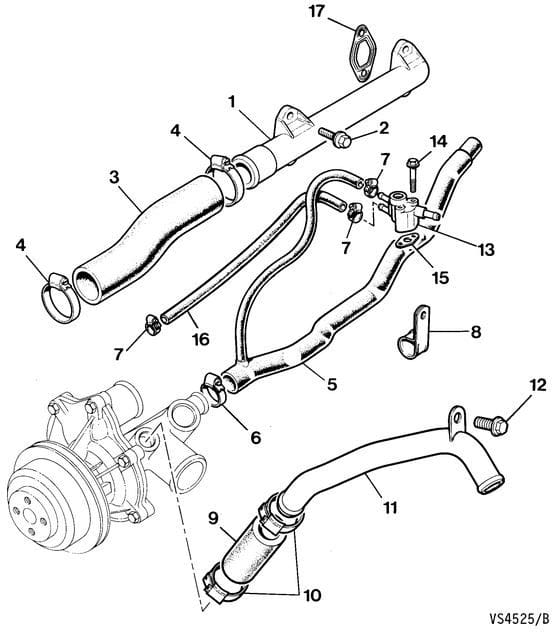
I'm wondering if what you are identifying as a CVV or PCV is actually just a fitting on the air intake where a crankcase breather hose connects, or one of the components in the diagram below?
In the XJ40, there is no valve in the crankcase breathing system at all. There is a restrictor, Part 10 in the diagram, which is just a ferrule with a hole of smaller diameter than the hose itself to limit negative pressure in the crankcase. There is also a coolant-heated restrictor, the part with three hose fittings labeled "Refer to Engine." Part 5 is a heater. It is hollow, but lined with copper or brass which heats up when electric current is applied.

If I recall correctly, the setup is identical on the '90-'92 cars and '93-'94 cars, with the exception that the late '94 cars may have the revised intake elbow used on the X300, with the Intake Air Temperature Sensor mounted ahead of the Idle Air Control Valve hose port instead of behind it.
Cheers,
Don
Last edited by Don B; 11-08-2020 at 10:33 PM.
#14
#15
Join Date: Feb 2014
Location: Crossroads of America
Posts: 19,415
Received 12,767 Likes
on
6,395 Posts
https://parts.jaguarlandroverclassic.../brand/jaguar/
Here's the diagram:

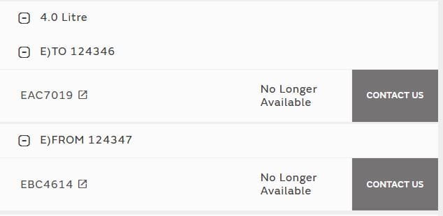
Here are the part numbers for the 4.0L engines:

Cheers,
Don
#16
#17
To follow-up on the search for the vacuum source for my heater valve; I removed the driver side (USA LHD) under scuttle pad
and the metal plate behind it. There are two vacuum lines behind the radio one single rubber hose that runs behind the radio to the right hand side and into the
vacuum tank/engine bay (?) and a T'd hard blue tinted plastic tube connected to silver metal vacuum motors (?) mounted on either end of the dashboard. The hard plastic line runs through a one way valve and is T'd to the same connection as the rubber line into the solenoid(?). I assume these lines are where I T my vacuum line to the heater valve. My assumption is the rubber hose is the better connection. Am I correct?
Thank you,
Roger
Last edited by Roger95; 01-06-2021 at 02:19 PM. Reason: clarification of question
#18
The following users liked this post:
Don B (01-06-2021)
#19
Thread
Thread Starter
Forum
Replies
Last Post
redtriangle
XJ6 & XJ12 Series I, II & III
10
01-06-2021 06:42 PM
Currently Active Users Viewing This Thread: 1 (0 members and 1 guests)


