When you click on links to various merchants on this site and make a purchase, this can result in this site earning a commission. Affiliate programs and affiliations include, but are not limited to, the eBay Partner Network.
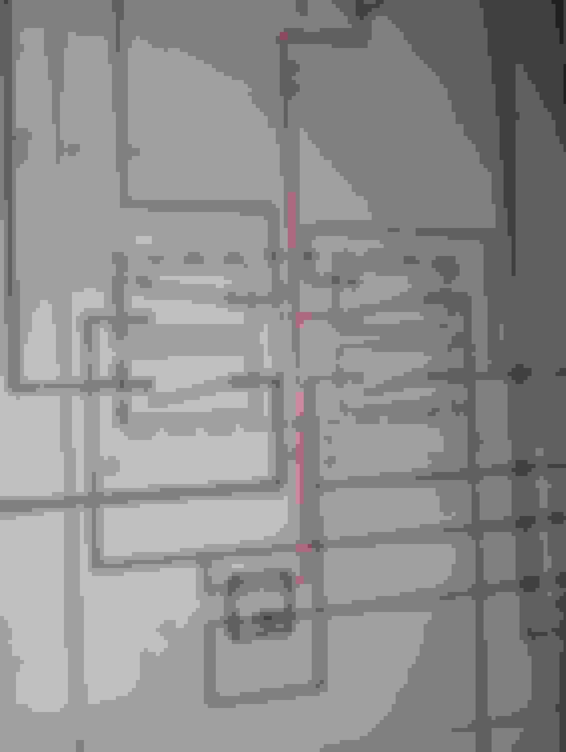
???? Help identify a part shown on the schematic????
What are the four rectangular boxes shown in this schematic? Relays?
I am most interested in the top and bottom left relays(?). The one with the green/pink/brown and the one with brown/yellow... Brown.... Red/white.
Also where are they on the car (87 xj6 left drive).
Thanks Dave. I have traced my no power issue back to the brown wire (female side) of the round connector that plugs into the amplifier. I thought maybe it was the master climate control switch per your schematic but the climate control switch operates when I disconnect and apply 12 volts directly to the Ranco thermostat. I am able to activate the blowers at the low/auto/hi/def (a, b, c, d per your schematic). Now I am thinking I have to back trace the brown wire. Yikes. Maybe I can jump 12 volts to the brown wire at the connector and see if it feeds power everywhere per the schematic? Thanks. Ren
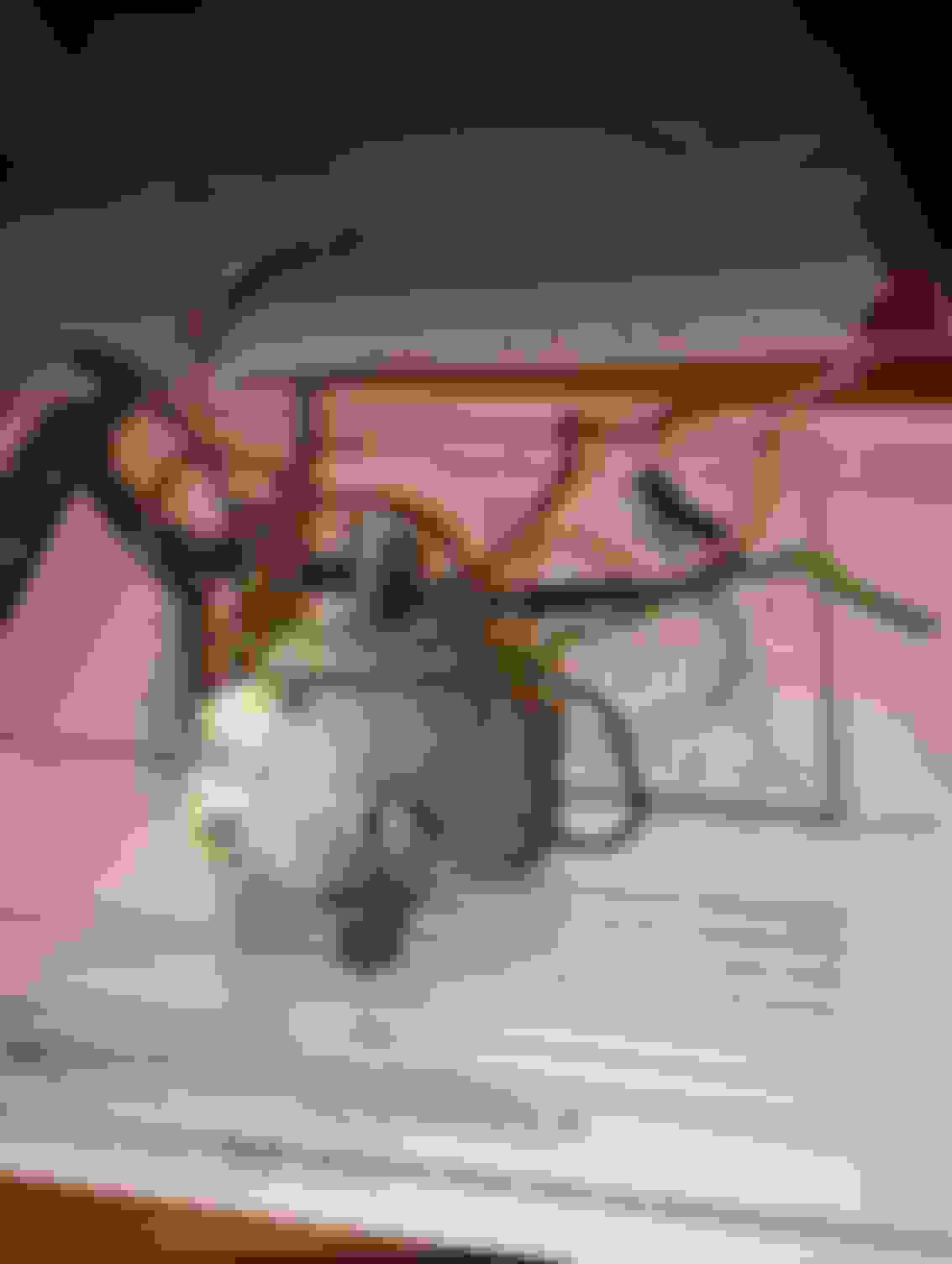
Dave (or anyone), I went to the junkyard and retrieved this Medusa looking climate control switch. It got me to thinking why there isn't a fifth switch for the auto setting called out in any schematic? Ren
I'm sorry Ren, I don't have an answer for that. I see what you mean on the schematic with A-D, but I can't tell you where the "auto" comes in------but I'll bet my next pay check that it does.
Someone much smarter than us will chime in and shed light.
Hi, don't know about being smarter, I bought 4 old Jags after all !
I'll assume you already have the Jag factory ROM - Book 12 ? ( Jose has it free on his site if not ).
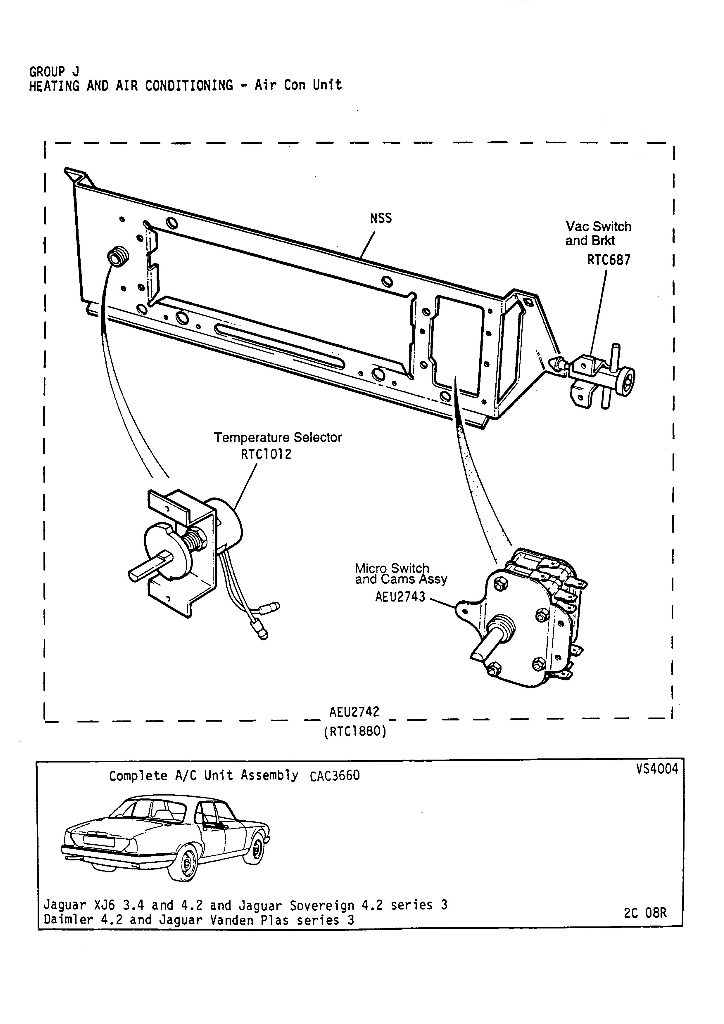
If you look at page 82-12 it has the switch position chart on the diagram I clipped below, the 4 switches are used in different combinations to make the 5 modes operate.
Off = A closed, B open, C open, D open
Low = A closed, B closed, C closed, D open
Auto = A closed, B open, C closed, D closed
Hi = A closed, B closed, C closed, D closed
Def = A open, B closed, C closed, D closed
The separate Delanair Mark II service manual goes into a better description / explanation than I can as to the purpose & operation on pages 29-32.
I also clipped the diagram showing the NO ( normally open ), NC ( normally closed ) positions with the wiring connections since it's kinda confusing to have a "open" switch making an electrical connection !
Hi, just realized that the diagram for the mode control switch Fig 26 showing the "actual" switch locations on the shaft has C & D backwards ! Don't have a switch to inspect right now to figure out whats correct, so beware and check the wire colors to make sure !
Brian: thanks for the in depth information. i'll admit i am way over my head but will keep taking small bites of this information. as mentioned earlier, i have no function at the climate control switch. i have been following the step by step directions given by allen (novo2001 who i found on youtube as allen makes a version of the amplifier) checking various fuses and applying power as indicated. allen suspected the switch itself as the culprit after i applied 12 volts via jumper to the brown wire pin on the backside of the connected amplifier with the key set on accessory. after doing so i heard the compressor click and i had blowers working at the auto/hi/defrost setting (i could feel the volume of air change as i moved from auto/hi to defrost). i did NOT have any blower at the low setting.
i hope it's the switch as it's a big job to remove it. got to remove the entire console and a bunch of stuff to finally get it out. i wish i could just remove and attach each of the 10 or 12 switch wires to the salvaged switch. what a bugger.
Any advice would be appreciated. I'd recommend finding novo2001 you tube post regarding his amplifier solution. not for everyone but he is very inventive.
ren
novom2001
Last edited by retroren; Jun 6, 2022 at 06:49 AM.
Reason: clarify
Hi
Some years ago I had problems with the mode switch on my XJ12. I was able to remove the control switch and replace the individual microswitches that are operated by the cams in the mode switch. The microswitches are a very common type, easily available from any electronics shop like Radio Shack. You will need the variant of switch that has the correct operating lever, which I think is a long straight bar, and the correct terminals which I think are for a spade type push on connector.
Can I also recommend reading Kirby Palm's excellent free book, "XJ-S: Experience in a book". It is still available (I think) to download on the Jag-Lovers website. It has a comprehensive section on the aircon, Delanair Mk II, which is shared across XJ-S, XJ6 and XJ12.
Pete M
Last edited by Pete M; Jun 8, 2022 at 03:20 PM.
Reason: Added info