When you click on links to various merchants on this site and make a purchase, this can result in this site earning a commission. Affiliate programs and affiliations include, but are not limited to, the eBay Partner Network.
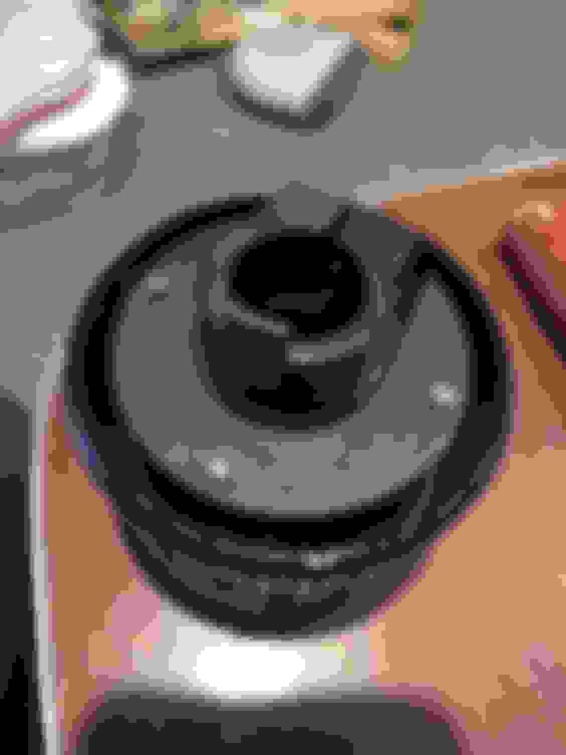
I have the steering mostly back together but the exact order of some elements is not clear. Does the retainer plate go on the cylinder piece (four screws holes on back but plate is only shaped for three so got a whole hole free) at what point? Before you screw it on seems to preclude it retaining anything but after it is on getting the screws in becomes impossible.
Then this plastic bracket ... i have seen it before but now at a loss and it's not in the diagrams.... something cylindrical does in the middle I can say for sure
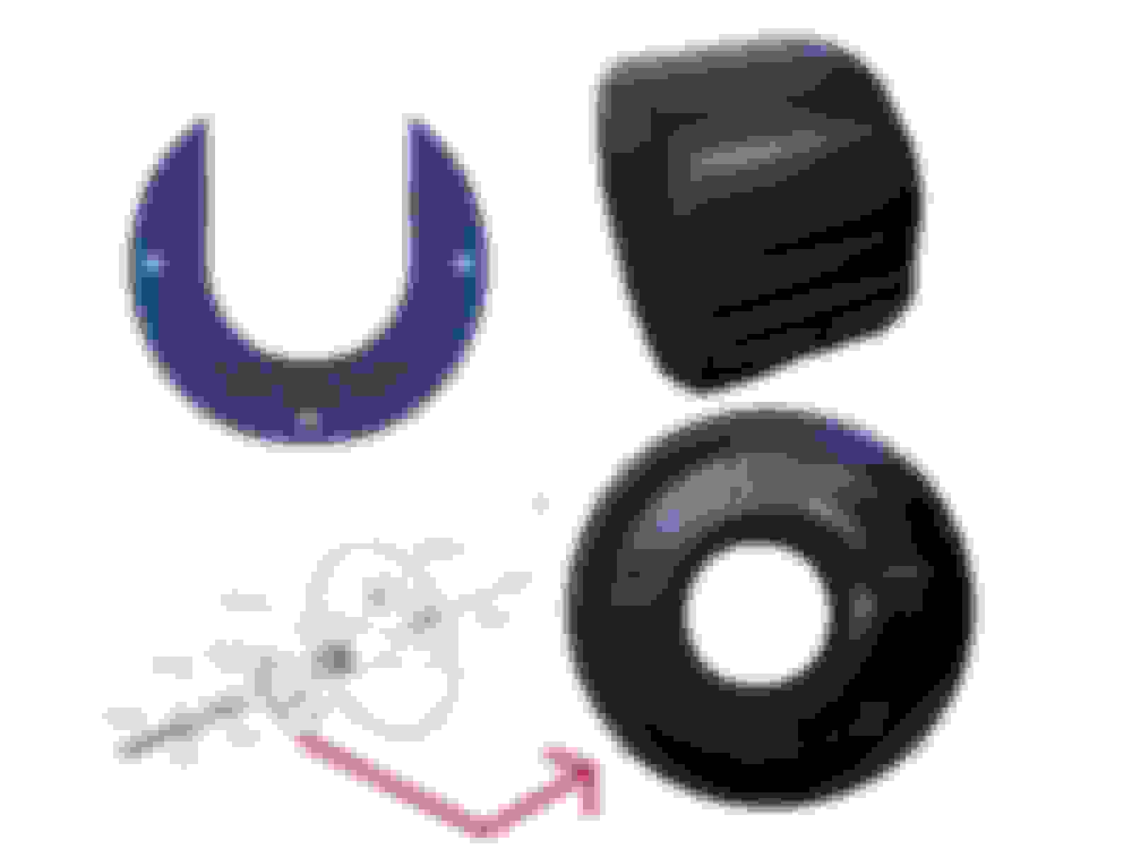
retainer plate and cylinder screw on thing hoop bracket .. er thing
the last picture is the ignition switch's fascia clamp.
not sure about the two pieces in the first picture but one could be a grommet for the floor where the column goes through the firewall.
- ha so the ignition switch's fascia clamp would be one of the latter/last thing to reattach then? goes on once the ignition and it parts all in place.?
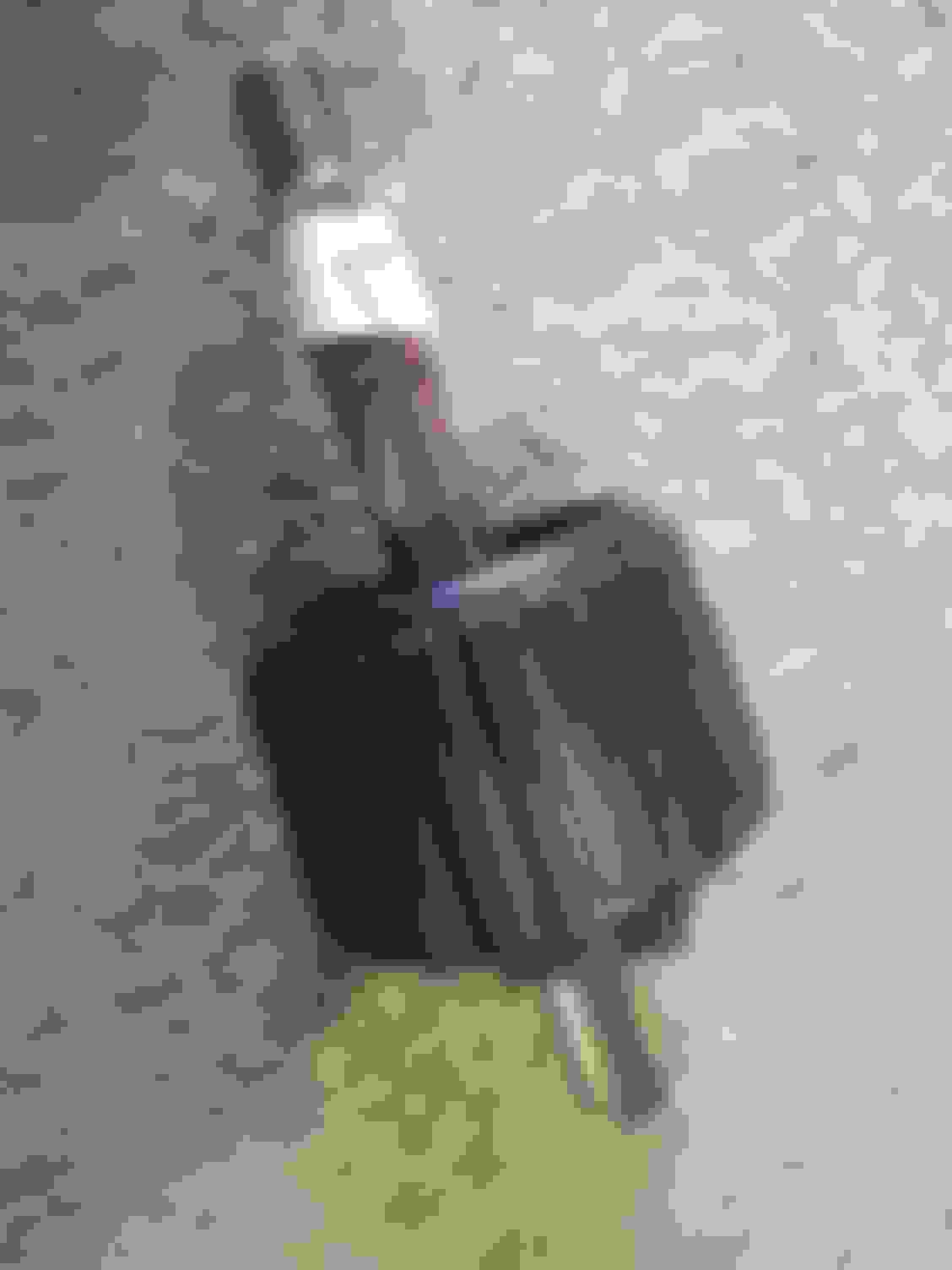
the other piece is section beneath horn plate and steering wheel, just can't figure how the retainer attaches either first or last and if last then how
It does a bit, I have a few diagrams showing a similar process but it's the stage at which one reattaches the retainer plate with 'cheesehead' screws to the locknut and how one does that in position as there is no room to reattached once in place but if reattached prior i cant figure what the retained plate would 'retain' if it were just being forced on atop the locknut section. I might be over thinking it but the logic of a retainer suggest retention or prevention of motion of some part and i cant figure how that is to happen.
maybe i need to remove more of the column again and assemble some of it in a different order.
If as per the diagram (2) the retain plate goes before (3) collect adaptor I'm stuffed if I can figure how to attached the cheesehead screws once that is in place.
Last edited by adenshillito; Aug 7, 2021 at 06:51 PM.
Reason: additional detail
I agree, the narrative in the shop manual is not intuitive, things don't seem to stack logically. I just recently replaced the steering wheel on mine with another compatible Jaguar wheel. Simple 5min job and I didn't get in far enough to see most of the stuff shown in the diagram.
Exploded diagrams are very good for gathering your parts in the approximate order, but they're a little like a cake recipe with no combining and cooking instructions. wrong order and you end up with a flat burnt cake.
The trick appears to be that the entirely hand-lock section needs to be assembled with the bolt (collecting stop button?) inside and then retainer attached and secured with the cheesehead screws x3 and the column bar through the centre to the collect adaptor. Then place into the main steering column maybe using a strand of wire to guide the cooper horn wire into place (but like with schroeder's moggie you'll not know if it's dead or alive inside the box) and then insert set screw into the collect adaptor and finally the bolt through the adapter and secured at other end. ... then on to next problem.
all together before attempting to connect to steering column retainer secured with 'cheesescrews'