
Series 1 Air con. Where to start. Or is best left to a professional? HOW TO


Joined: Feb 2010
Posts: 28,814
Likes: 11,280
From: Adelaide Stralia
My understanding, and what has worked for me on these cars is:
Power from the on/off switch, whatever fancy, or lack of fancy that may be, to the thermostat, then from the thermostat to the pressure switch. Other side of pressure switch to the supply of the compressor. That supply TO the compressor is to the electro clutch on the front, and a 2nd (black) wire is the earth, and is usually attached to the compressor casing.
Since the MK4 has the on/off switch as part of the thermostat switch, there will be ONE wire coming from the MK4 unit which will follow the path I mentioned above, minus the thermostat.
Finger tight, bugga. Someone did a bodge on that one by the sounds of it.
Thread Starter
|
Joined: Jan 2014
Posts: 28,386
Likes: 6,340
From: Delaneys Creek,Qld. Australia
My understanding, and what has worked for me on these cars is:
Power from the on/off switch, whatever fancy, or lack of fancy that may be, to the thermostat, then from the thermostat to the pressure switch. Other side of pressure switch to the supply of the compressor. That supply TO the compressor is to the electro clutch on the front, and a 2nd (black) wire is the earth, and is usually attached to the compressor casing.
Since the MK4 has the on/off switch as part of the thermostat switch, there will be ONE wire coming from the MK4 unit which will follow the path I mentioned above, minus the thermostat.
Finger tight, bugga. Someone did a bodge on that one by the sounds of it.
Power from the on/off switch, whatever fancy, or lack of fancy that may be, to the thermostat, then from the thermostat to the pressure switch. Other side of pressure switch to the supply of the compressor. That supply TO the compressor is to the electro clutch on the front, and a 2nd (black) wire is the earth, and is usually attached to the compressor casing.
Since the MK4 has the on/off switch as part of the thermostat switch, there will be ONE wire coming from the MK4 unit which will follow the path I mentioned above, minus the thermostat.
Finger tight, bugga. Someone did a bodge on that one by the sounds of it.
Bodge was the PO's middle name.
Bodge job
A job that was completed quickly and carelessly, possibly with one's mind on other things, or without using the correct tools, even if no mistakes were made.
Last edited by o1xjr; May 11, 2015 at 07:33 AM.

Veteran Member
Joined: Jul 2012
Posts: 6,796
Likes: 2,403
From: Walnut Creek, California
Gotta love that repurposed puddle jumper. crude as it is, it beats going to the wrecker!!!
Reminds me of the old MG sedan that was given me because of right front collision damage and serious back DMV fees. Stripped, almost to the pan, and with some big bald tires, it became a passable "sand buggy".
Carl
Carl
Reminds me of the old MG sedan that was given me because of right front collision damage and serious back DMV fees. Stripped, almost to the pan, and with some big bald tires, it became a passable "sand buggy".
Carl
Carl

Veteran Member


Joined: Mar 2014
Posts: 26,764
Likes: 10,312
From: Tehama County, California, USA
I kind of think those cores need ALL their fins or they wouldn't be built with them. Straightening them has Got to improve performance!
(';')
Bravo Clarke 
What an awesome effort. You found the main problem already! I wonder why it was disconnected in the first place? A major leak they couldnt find or perhaps something failed and they couldnt afford to replace it?
Mate whilst you got it in pieces I would do the following as a matter of being doubly sure:
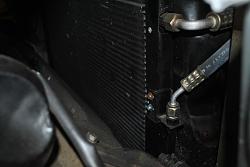
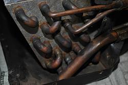
* trace out all the piping/hoses in entire circuit. So thats evaporator (inside your dash) to compressor. Compressor to Condensor (out side rad grille) and condensor back to Tx valve, tx valve to evaporator. Just make sure it's all in tact. We'll soon find out once we pull a vaccum on it. No sense putting all that gas in if she's gonna leak out again. Remember, an air con system doesn't "USE" a little gas , it leaks it.
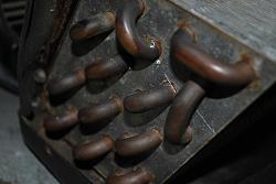
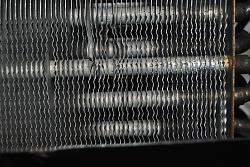
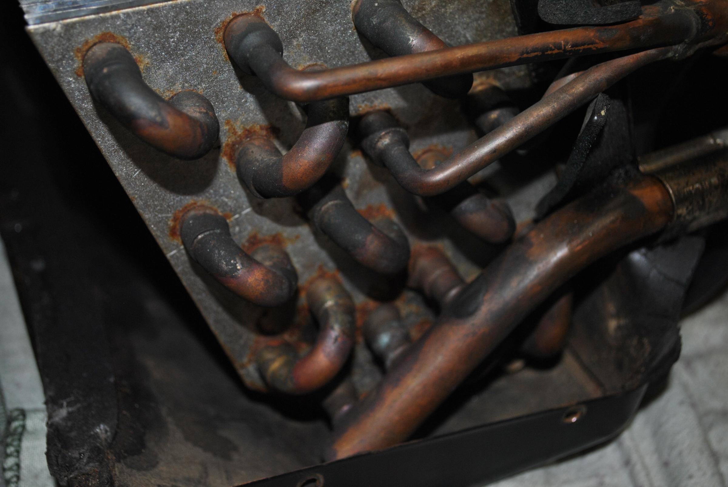
* Sounds like you already are but check condition of evaporator and condensor fins. Make sure their not busted (will leak gas) and straighten them out with the comb as you already did above. Look for any signs of the coil being opened up.
* Check belt on compressor clutch.
* A tell tale signs for leaks is evidence of oil residue around piping etc but being that it hasn't run for ages AND it is in a car engine bay, its probably pretty hard to pick up.
Mate you mentioned only one wire going to the compressor? Must use the housing of the compressor to return via the chassis. Just make sure there is a return (negative) path somewhere around there. Maybe it is missing?
Yeah you got it right. That component is a diode. It may be used to stop current flowing back towards the relay, not sure. If you have your meter across it in diode mode, black lead to Cathode (end with the silver stripe), Red lead to anode, you should get aroud 1.4V's (or 0.7V's depending on diode type) across it. If you get open circuit or complete short we'll source you another.
What an awesome effort. You found the main problem already! I wonder why it was disconnected in the first place? A major leak they couldnt find or perhaps something failed and they couldnt afford to replace it?
Mate whilst you got it in pieces I would do the following as a matter of being doubly sure:
* trace out all the piping/hoses in entire circuit. So thats evaporator (inside your dash) to compressor. Compressor to Condensor (out side rad grille) and condensor back to Tx valve, tx valve to evaporator. Just make sure it's all in tact. We'll soon find out once we pull a vaccum on it. No sense putting all that gas in if she's gonna leak out again. Remember, an air con system doesn't "USE" a little gas , it leaks it.
* Sounds like you already are but check condition of evaporator and condensor fins. Make sure their not busted (will leak gas) and straighten them out with the comb as you already did above. Look for any signs of the coil being opened up.
* Check belt on compressor clutch.
* A tell tale signs for leaks is evidence of oil residue around piping etc but being that it hasn't run for ages AND it is in a car engine bay, its probably pretty hard to pick up.
Mate you mentioned only one wire going to the compressor? Must use the housing of the compressor to return via the chassis. Just make sure there is a return (negative) path somewhere around there. Maybe it is missing?
Yeah you got it right. That component is a diode. It may be used to stop current flowing back towards the relay, not sure. If you have your meter across it in diode mode, black lead to Cathode (end with the silver stripe), Red lead to anode, you should get aroud 1.4V's (or 0.7V's depending on diode type) across it. If you get open circuit or complete short we'll source you another.
Last edited by paulyling; May 11, 2015 at 05:44 PM.

Veteran Member
Joined: Jan 2012
Posts: 1,174
Likes: 743
From: Sunshine Coast QLD
My guess is the Diode is connected to the fan (not blower under the dash) and would allow activating the Fan when the ac is on.
The diode would be to prevent the fan activating the AC when it is triggered by the water temp switch
But then again if you dont have an aux fan im wrong !!!
We can trace out the wiring when we vac down the system. If anything needs fixing I have everything here we will need including a bunch of diodes
PS I have a few new aux fans here of various sizes so if my guess is wrong and you don't have an aux fan lets fit one!!!
Cheers
34by151
Thread Starter
|
Joined: Jan 2014
Posts: 28,386
Likes: 6,340
From: Delaneys Creek,Qld. Australia
Paul & James, Answers to your questions.
Hose from condenser to compressor is like new (date stamp 7/2010)
Hose from compressor to evaporator is like new (date stamp 9/2009) R134a Air con hose
Hose from evaporator to receiver/dryer is like new (date stamp 6/09)
Hose from receiver/drier to condenser is like new (date stamp 6/09)
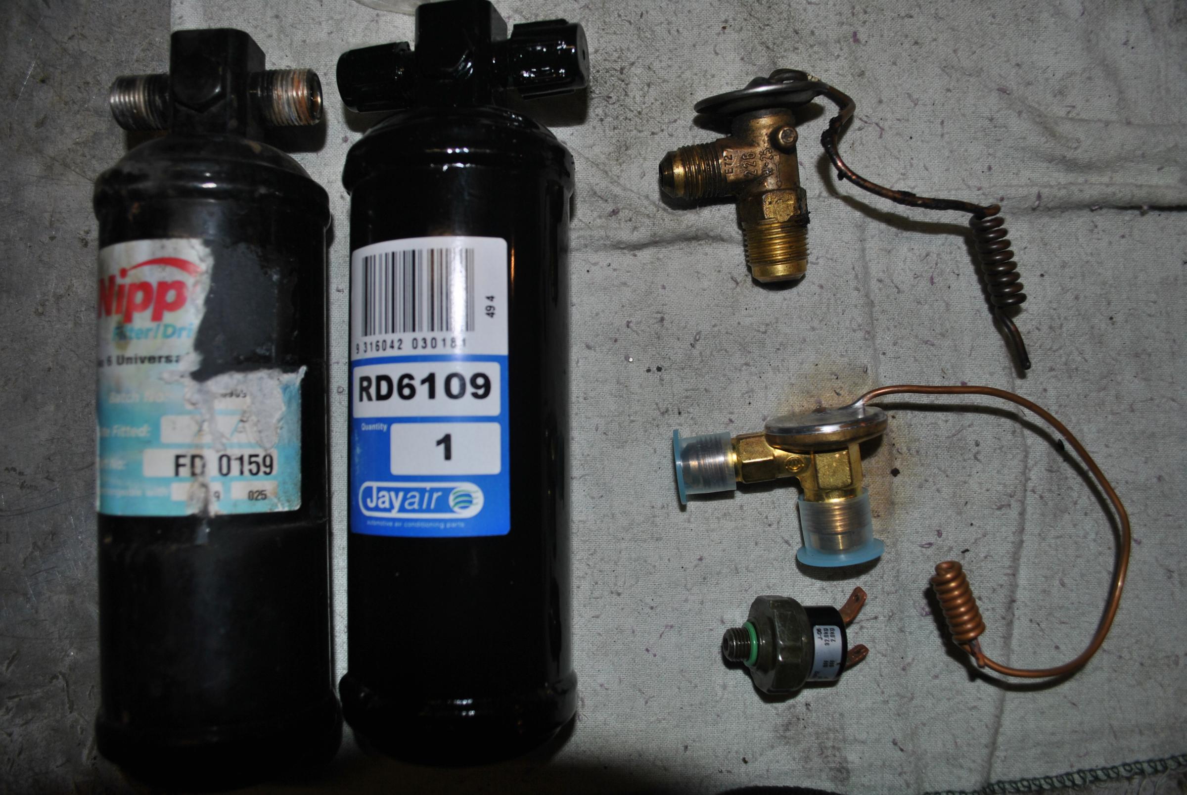
Picking up new TX valve and receiver dryer today.
Condenser looks like a recent job too,all fins look perfect and paint looks near new. I'm assuming someone attempted to rebuild this system between 2010 and late 2013 when I got the car.
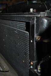
Evaporator fins and core look pretty good,no signs of cracks or leaks.

I put all new belts on when I replaced the water pump recently. No evidence of oily residue anywhere around air con system at all. No oily residue in that engine bay except a small weep around the valve cover.
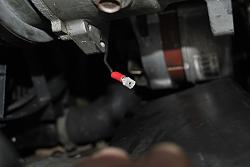
This is the only wire on the compressor(goes into the clutch), it connects to the anode end of the diode. No sign of any other wire or connector I can see.
I took the diode to Jaycar and they tested it, it had a reading of 480?
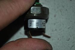
I tested it on my Supercheap meter today before I fixed up the harness for refitting,see pic below for reading. Don't know if I had it set right,electrical stuff is not my strong point.


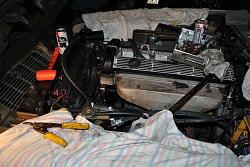
Yes, I have twin AU Falcon fans fitted,original fan removed. You can see relay on top left of the fan housing.
Only thing I haven't done is tested the compressor,can I do this with the switches disconnected and removed?
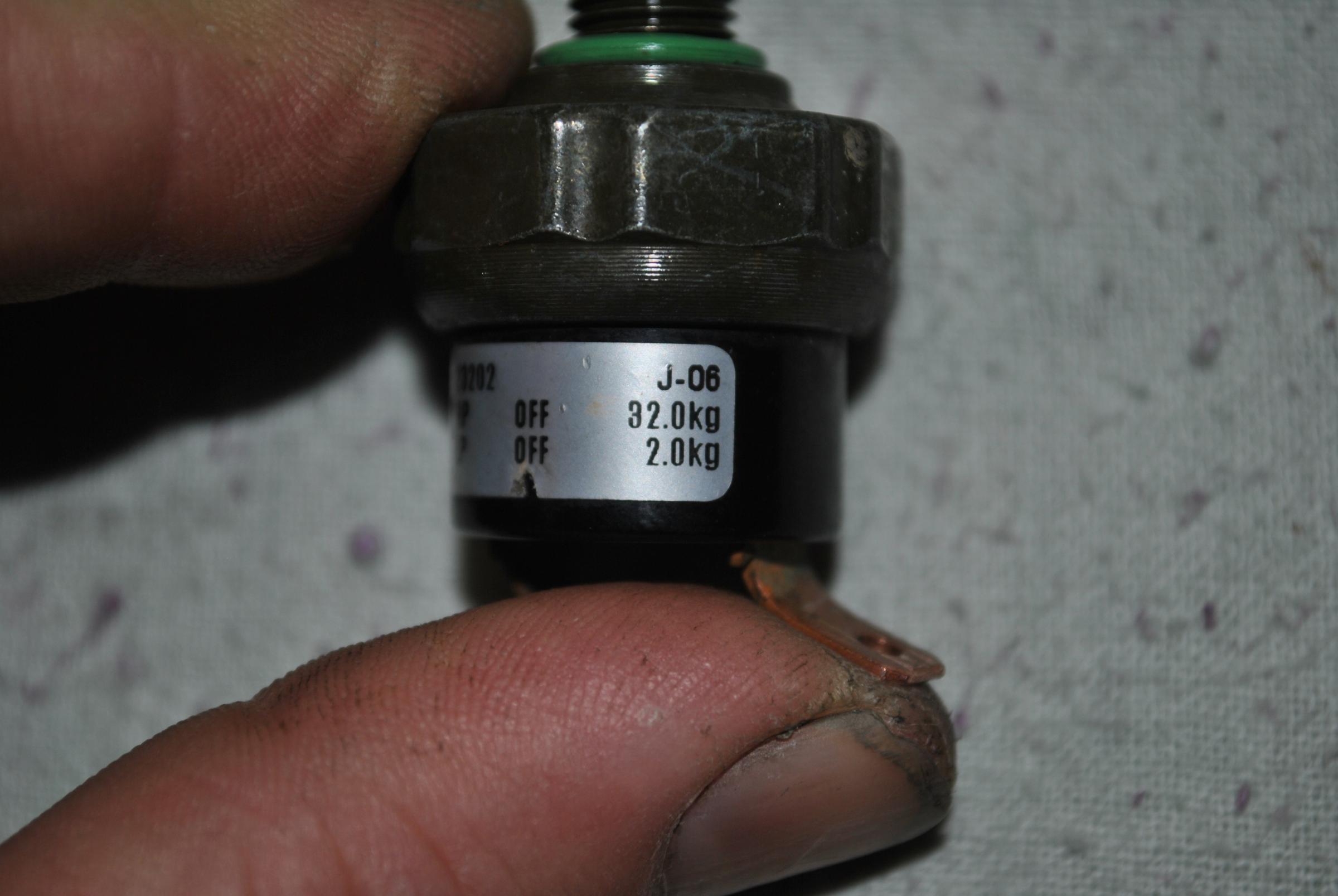
Is there any way to test the pressure switch? it has HP off 32kg/LP off 2kg.

Hose from condenser to compressor is like new (date stamp 7/2010)
Hose from compressor to evaporator is like new (date stamp 9/2009) R134a Air con hose
Hose from evaporator to receiver/dryer is like new (date stamp 6/09)
Hose from receiver/drier to condenser is like new (date stamp 6/09)
Picking up new TX valve and receiver dryer today.

Condenser looks like a recent job too,all fins look perfect and paint looks near new. I'm assuming someone attempted to rebuild this system between 2010 and late 2013 when I got the car.


Evaporator fins and core look pretty good,no signs of cracks or leaks.


I put all new belts on when I replaced the water pump recently. No evidence of oily residue anywhere around air con system at all. No oily residue in that engine bay except a small weep around the valve cover.
This is the only wire on the compressor(goes into the clutch), it connects to the anode end of the diode. No sign of any other wire or connector I can see.

I took the diode to Jaycar and they tested it, it had a reading of 480?
I tested it on my Supercheap meter today before I fixed up the harness for refitting,see pic below for reading. Don't know if I had it set right,electrical stuff is not my strong point.


Yes, I have twin AU Falcon fans fitted,original fan removed. You can see relay on top left of the fan housing.


Only thing I haven't done is tested the compressor,can I do this with the switches disconnected and removed?
Is there any way to test the pressure switch? it has HP off 32kg/LP off 2kg.

Last edited by o1xjr; May 11, 2015 at 08:06 PM.
Great work bud
The diode reading you are getting on your multimeter is in millivolts. So the diode has about a 0.5V (500mV) forward bias? Sounds about right. It needs that amount of voltage across it for it to start to conduct and allow current flow from Anode to Cathode. It depends on exactly what type of diode but typical 0.7V (700mV) and for power diodes as much as 1.4V . So long as she isnt shorted or open circuit is the main thing. I think you can tick that one off so long as it is crimped/soldered in the circuit properly.
I'm not real sure what a good hack is to test the pressure switch. Does anybody know what a typical resistance these give out of circuit?
In regards to the compressor. I suppose you could briefly jump a lead from 12V to the + terminal of the compressor (assuming the negative is connected the via chassis) but you may risk stuffing up the compressor as their is no gas in the system (hence what the low pressure cut out is for). Can somebody confirm?
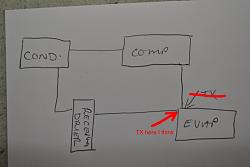
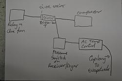
Clarke I also attached a basic diagram (from my old text book) of the main elements in the automotive air con system to help you with your diagram. I dont think yours has an Accumulator (not sure) and also just so you know the TX valve should just be before the evaporator. This is the cooled off liquid coming back from the condensor. Once it goes through the TX valve it starts to come out as mostly vapour with a bit of liquid. By the time it passes through your evaporator it should then be all vapour which carriers all the heat from your car with it, being sucked then to the low side of the compressor.
Compressor shoots out higher pressure liquid to the condensor, which the liquid then gets cooled as it passes through the condensor coil. After it goes through the receiver she comes back to the TX valve, out again and the cooled vapour in the evaporator gets its "coolness" blown to the driver via the blower fan and so on.....lather rinse repeat
I bet you know more about automotive A/C's now than you did last week bud!
The diode reading you are getting on your multimeter is in millivolts. So the diode has about a 0.5V (500mV) forward bias? Sounds about right. It needs that amount of voltage across it for it to start to conduct and allow current flow from Anode to Cathode. It depends on exactly what type of diode but typical 0.7V (700mV) and for power diodes as much as 1.4V . So long as she isnt shorted or open circuit is the main thing. I think you can tick that one off so long as it is crimped/soldered in the circuit properly.
I'm not real sure what a good hack is to test the pressure switch. Does anybody know what a typical resistance these give out of circuit?
In regards to the compressor. I suppose you could briefly jump a lead from 12V to the + terminal of the compressor (assuming the negative is connected the via chassis) but you may risk stuffing up the compressor as their is no gas in the system (hence what the low pressure cut out is for). Can somebody confirm?
Clarke I also attached a basic diagram (from my old text book) of the main elements in the automotive air con system to help you with your diagram. I dont think yours has an Accumulator (not sure) and also just so you know the TX valve should just be before the evaporator. This is the cooled off liquid coming back from the condensor. Once it goes through the TX valve it starts to come out as mostly vapour with a bit of liquid. By the time it passes through your evaporator it should then be all vapour which carriers all the heat from your car with it, being sucked then to the low side of the compressor.
Compressor shoots out higher pressure liquid to the condensor, which the liquid then gets cooled as it passes through the condensor coil. After it goes through the receiver she comes back to the TX valve, out again and the cooled vapour in the evaporator gets its "coolness" blown to the driver via the blower fan and so on.....lather rinse repeat
I bet you know more about automotive A/C's now than you did last week bud!
Last edited by paulyling; May 12, 2015 at 03:30 AM.
Joined: Feb 2010
Posts: 28,814
Likes: 11,280
From: Adelaide Stralia
Told ya it was simple.
The disconnected hoses, and finger tight, simply lost me.
Not sure why a MK4 would have a diode in the first place?
Supplying 12v to the compressor "should" activate the clutch, indicated by a distinctive CLICK. No harm will come of anything if the engine is NOT running.
The disconnected hoses, and finger tight, simply lost me.
Not sure why a MK4 would have a diode in the first place?
Supplying 12v to the compressor "should" activate the clutch, indicated by a distinctive CLICK. No harm will come of anything if the engine is NOT running.
Thread Starter
|
Joined: Jan 2014
Posts: 28,386
Likes: 6,340
From: Delaneys Creek,Qld. Australia
Just jumped the compressor off the battery,a distinctive click there.
New Receiver/drier and TX valve, also ordered a pressure switch while I was there($20). It was a XA-XF Falcon job.
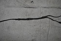
I thought while I was playing around in this area I would tidy up some of a PO's wiring. So cut open this bulb with wires coming out of it because it looked like a whole heap of wasted wire wrapped in tape.
Attachment 111892
So when I got it apart it had this thingy(for want of a better term), with a dodgy wiring/connector set up.
Attachment 111893Attachment 111894
So it turns out the "thingy" is called a diode and it is directional too. I tested it with a multi meter but it would not register anything so I took it to Jaycar(our Aussie know it all electrical and connector shop). Turns out I was putting the + & - probes on the wrong ends of it. I even learnt that my multi meter has a setting for testing diode's.
So how doe's this work and what doe's it do? The wire with the red connector comes from the relay on the thermo fan then passes through the diode, then it has 2 wires, one goes to the pressure switch on the receiver/drier, the other goes to the compressor. From what I can see it is the only wire going to the compressor? is that right? My wiring diagram shows just one wire coming from the thermo manual switch which I assume this is, and a ground which I assume is the bracket to the water pump and block.
Attachment 111895Attachment 111896Attachment 111897
Sorry, a lot of questions. But as usual I have jumped into a project hoping for the best.
Since I have joined JF my projects have worked out better faster than expected because I use to spend half my days off driving around to talk to people that might give me the right advice. Now it just arrives at my laptop.
A forward biased diode also drops about a volt in the circuit. Its possible (though less likely) they may have been trying to drop peak voltage to the downstream items.
Both these ideas seem a bit dont blend well with how things have been implemented in that "thingy" area (surely if you knew these things you would do a better job.....unless his mate said try this and thats what he came up with). Its often hard to understand why previous owners do some of the things we discover. I was watching a car show once and the guy was fixing some botch up and he was saying he really didnt mind doing the work but he would really like to know what was going through the persons mind, because he couldnt make up a universe where it made any sense on any level.
Last edited by yarpos; May 11, 2015 at 10:21 PM.
Veteran Member
Joined: Jan 2012
Posts: 1,174
Likes: 743
From: Sunshine Coast QLD
As I guessed the diode was put in place to trigger the Aux Fan
You will find the the Aux fan relay is wired to a temp switch to aid in engine cooling
The Diode prevents the AC clutch engaging when the coolant temp switch enables the relay.
The diode however enables the relay when you turn on the AC
Cheers
34by151
You will find the the Aux fan relay is wired to a temp switch to aid in engine cooling
The Diode prevents the AC clutch engaging when the coolant temp switch enables the relay.
The diode however enables the relay when you turn on the AC
Cheers
34by151
Thread Starter
|
Joined: Jan 2014
Posts: 28,386
Likes: 6,340
From: Delaneys Creek,Qld. Australia
As I guessed the diode was put in place to trigger the Aux Fan
You will find the the Aux fan relay is wired to a temp switch to aid in engine cooling
The Diode prevents the AC clutch engaging when the coolant temp switch enables the relay.
The diode however enables the relay when you turn on the AC
Cheers
34by151
You will find the the Aux fan relay is wired to a temp switch to aid in engine cooling
The Diode prevents the AC clutch engaging when the coolant temp switch enables the relay.
The diode however enables the relay when you turn on the AC
Cheers
34by151
There is a temp switch on the right side of the fan housing with an adjustable knob(like a volume control) I assume this is to adjust the temp the fan comes on.
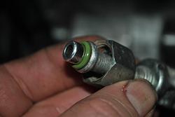
The Hichill cans have a different connection to the gas cylinders, here a couple of pictures of the adapter. Do you have something for this or do I need to get one as well? When I get the gas.
The oil for the compressor comes in 1 litre (with die), will that be enough?


Veteran Member
Joined: Jan 2012
Posts: 1,174
Likes: 743
From: Sunshine Coast QLD
I assume we will need the adapter
My gauges (for the gas/vac) have a 5/16 fitting
I have a tank fitting for a Std gas tank (4.5/9kg) but it sounds like this wont fit
AIR Manifold Gauge Tool SET Conditioning Refrigeration R134A R410A Refrigerant | eBay
Cheers
34by151
My gauges (for the gas/vac) have a 5/16 fitting
I have a tank fitting for a Std gas tank (4.5/9kg) but it sounds like this wont fit
AIR Manifold Gauge Tool SET Conditioning Refrigeration R134A R410A Refrigerant | eBay
Cheers
34by151
Thread Starter
|
Joined: Jan 2014
Posts: 28,386
Likes: 6,340
From: Delaneys Creek,Qld. Australia
As I guessed the diode was put in place to trigger the Aux Fan
You will find the the Aux fan relay is wired to a temp switch to aid in engine cooling
The Diode prevents the AC clutch engaging when the coolant temp switch enables the relay.
The diode however enables the relay when you turn on the AC
Cheers
34by151
You will find the the Aux fan relay is wired to a temp switch to aid in engine cooling
The Diode prevents the AC clutch engaging when the coolant temp switch enables the relay.
The diode however enables the relay when you turn on the AC
Cheers
34by151
Then got it hot enough for the fans to start and no power going to the compressor or pressure switch.
This electrical stuff isn't so confusing once explained.

Thread Starter
|
Joined: Jan 2014
Posts: 28,386
Likes: 6,340
From: Delaneys Creek,Qld. Australia
I assume we will need the adapter
My gauges (for the gas/vac) have a 5/16 fitting
I have a tank fitting for a Std gas tank (4.5/9kg) but it sounds like this wont fit
AIR Manifold Gauge Tool SET Conditioning Refrigeration R134A R410A Refrigerant | eBay
Cheers
34by151
My gauges (for the gas/vac) have a 5/16 fitting
I have a tank fitting for a Std gas tank (4.5/9kg) but it sounds like this wont fit
AIR Manifold Gauge Tool SET Conditioning Refrigeration R134A R410A Refrigerant | eBay
Cheers
34by151
Hoses Come with Brass 1/4" & 5/16"Sae Fittings Fittings
Veteran Member
Joined: Jan 2012
Posts: 1,174
Likes: 743
From: Sunshine Coast QLD
The lines have 1/4 on one end and 5/16 on the other
the 1/4 end connects to the manifold so the gas/vac line has 5/16 as does the connection to the schrader valve adapters
Cheers
34by151
the 1/4 end connects to the manifold so the gas/vac line has 5/16 as does the connection to the schrader valve adapters
Cheers
34by151
Thread Starter
|
Joined: Jan 2014
Posts: 28,386
Likes: 6,340
From: Delaneys Creek,Qld. Australia
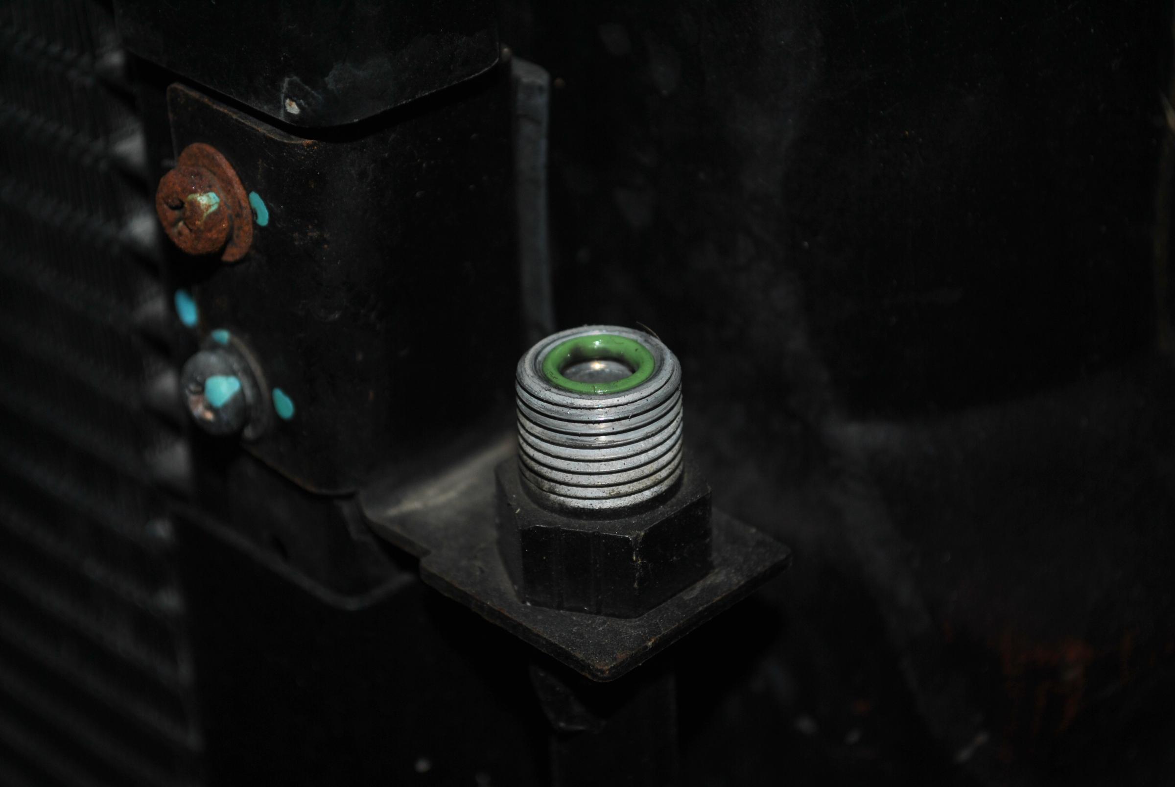
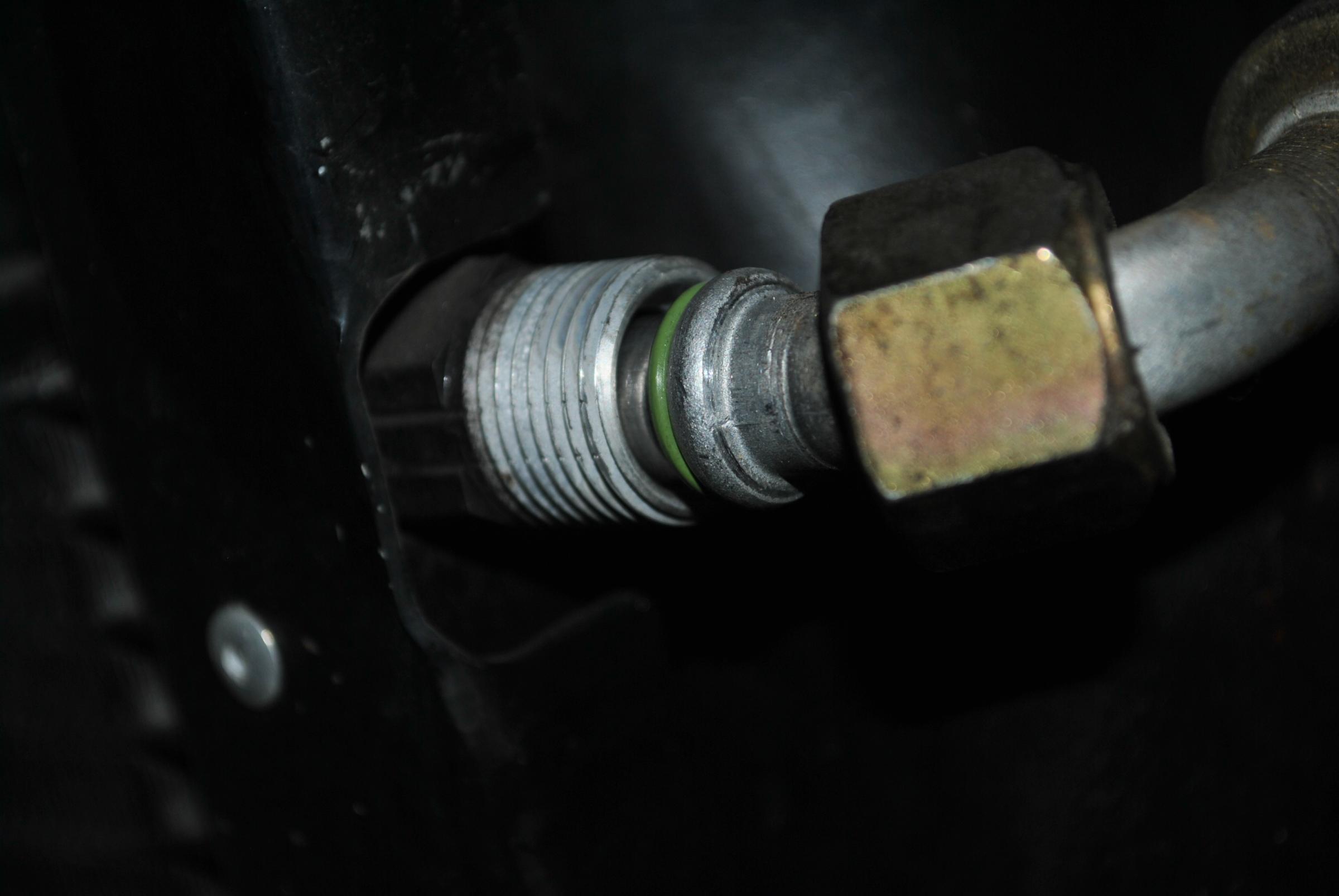
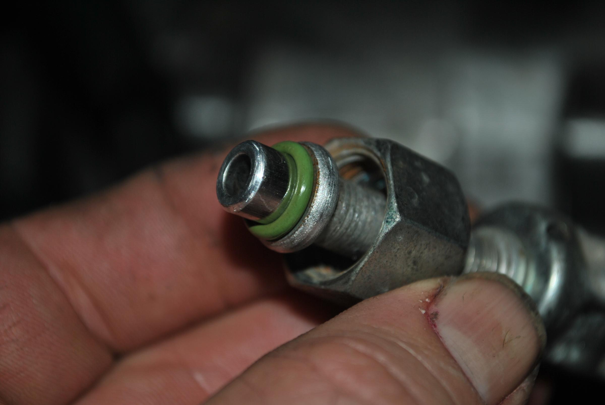
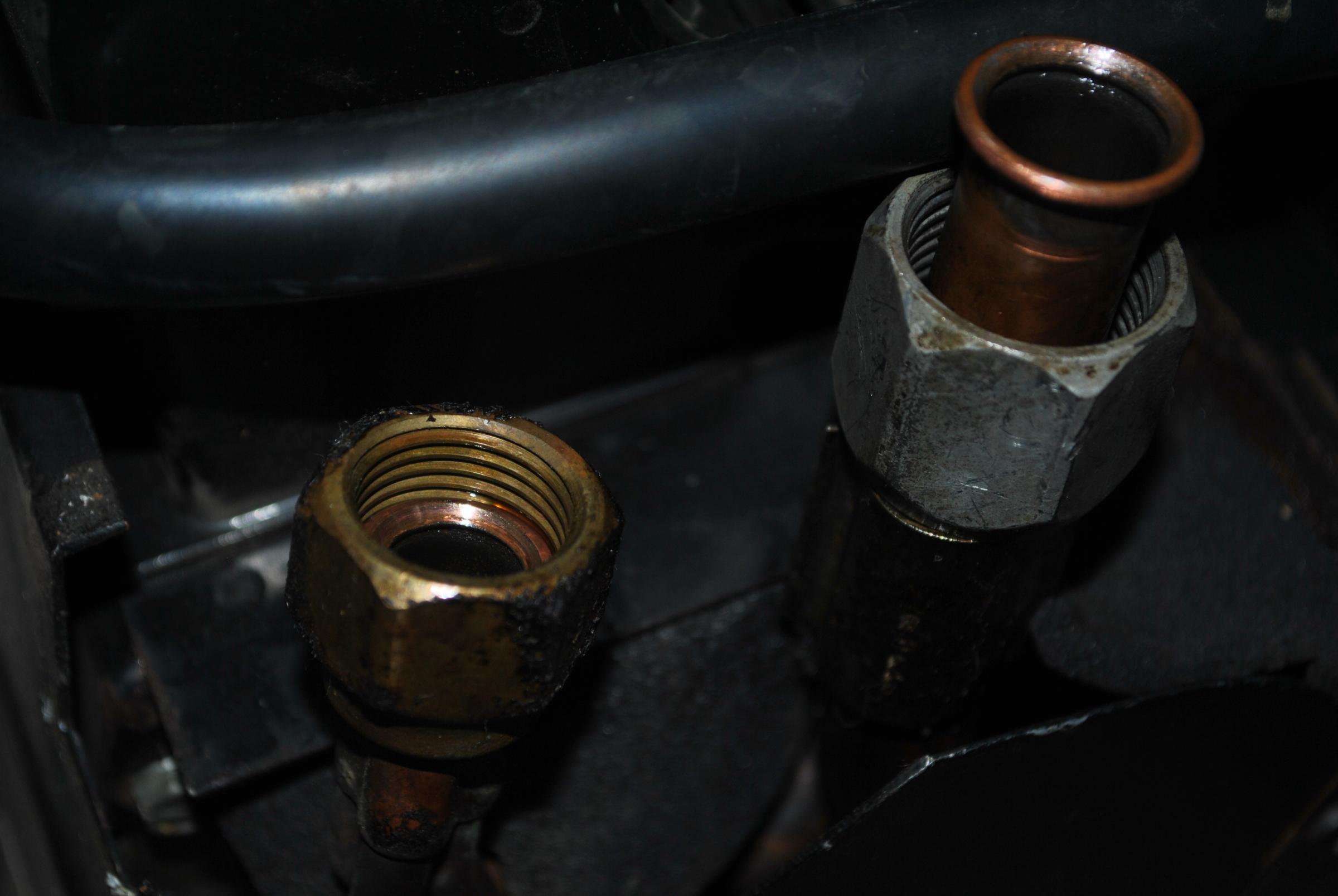
James, answer to your question is yes I do need o-rings. I will pick up what I need this week.
Hoses to condenser have O-rings.


Hoses to receiver drier have O-rings
Hoses to compressor ,no O-rings


Hoses to TX and evaporator , no O-rings


The ones without O-rings look like standard type hydraulic fluid connectors, I assume they don't need O-rings.
Hoses to condenser have O-rings.
Hoses to receiver drier have O-rings
Hoses to compressor ,no O-rings


Hoses to TX and evaporator , no O-rings

The ones without O-rings look like standard type hydraulic fluid connectors, I assume they don't need O-rings.

Junior Member
Joined: May 2015
Posts: 1
Likes: 2
From: Watford
In a couple of weeks time myself and fellow member paulyling  (Paul) are going to see if we can find out why my air con does not work. Paul has experience with industrial size air con units but not automotive.
The air has not worked since I have had the car (17 months). The PO told me it just needed a regas, but were a lot of small things that just needed a little work ..... 12 months and $6k later all works except the air.
The car was fitted with the air con at the dealer where it was sold new( found the original paperwork and service records book yesterday)
The only identifying thing on the unit is "Mark IV", it doe's not look like the two units pictured in manuals I have for series 1 cars.
The fan works and it blows ambient temp air, not sure what else doe's or doe's not work. Any pointers or ideas where to start would be a great help.
If it is something we cannot do I will eventually have it looked at by a mobile air con guy.
I have included some pictures, but if any more pics will help I will post what is needed.
Attachment 111598Attachment 111599Attachment 111600Attachment 111601Attachment 111602Attachment 111603Attachment 111604Attachment 111605Attachment 111606Attachment 111607
The air has not worked since I have had the car (17 months). The PO told me it just needed a regas, but were a lot of small things that just needed a little work
The car was fitted with the air con at the dealer where it was sold new( found the original paperwork and service records book yesterday)
The only identifying thing on the unit is "Mark IV", it doe's not look like the two units pictured in manuals I have for series 1 cars.
The fan works and it blows ambient temp air, not sure what else doe's or doe's not work. Any pointers or ideas where to start would be a great help.
If it is something we cannot do I will eventually have it looked at by a mobile air con guy.
I have included some pictures, but if any more pics will help I will post what is needed.
Attachment 111598Attachment 111599Attachment 111600Attachment 111601Attachment 111602Attachment 111603Attachment 111604Attachment 111605Attachment 111606Attachment 111607
I used to fit this type of air conditioning system to Jaguars back in the day. What do you need to know?
Roger
Thread Starter
|
Joined: Jan 2014
Posts: 28,386
Likes: 6,340
From: Delaneys Creek,Qld. Australia
So far from the input from members I have tested and checked most things, if there is something else we can check before we vacuum the system to see if it has no leaks that would be appreciated.
I can get hold of another blower/evaporator unit fairly cheap, but mine looks better condition. Is it worth spending $30 to have it on hand?