When you click on links to various merchants on this site and make a purchase, this can result in this site earning a commission. Affiliate programs and affiliations include, but are not limited to, the eBay Partner Network.
I've noticed this a few times lately. Sometimes, when I turn the car's headlights on, the dashboard instrument lights don't come on. The headlights themselves come on, and the indicator lights in the dash and all that show up, just not the ones that come on when you switch the headlights on. Loose connection somewhere, I'm guessing, but where? Dash itself, or the stalk? So far, it's more "erratic" than "often," let alone "always," but it might get that way. The instruments themselves are reading fine. But could this be an earth issue? The lights are all out, so I don't think it's a bulb issue.
At this stage, I'm thinking soldering an earth wire to the instrument panel interior (facelift version, so if anyone knows where that wire should be soldered, I'd love to know), and finding some place to screw that to some metal. Probably wouldn't hurt, at any rate.
Today, I turned the lights on after getting takeaways, then when I was indicating a right turn a little later, I noticed they'd gone out. Turned the lights on then off, and they came back on fine. Then, back home, I turned them off again, then on--and the instrument lights were dark, even if I turned the lights on and off a few times. Parked the car and tried again, and they were fine. So it's erratic, definitely.
Any suggestions, advice, warnings, etc. would, of course, be most gratefully received. I feel somewhat in the dark here....
Thanks for your suggestions. Now for a newbie question: what's the rheostat and where would I find it? This SITE suggests that the rheostat is the dial used to control the brightness of the lights. So that would mean THIS part (according to Jaguar Classic Parts). I can find that easily enough (and they have them in stock if I need to replace it.)
Doug's post HERE suggests simply splicing the wires together.
Remove the wires from the rheostat and splice them together or join them
together with a new length of wire and appropriate male spade connectors.
All you are doing is applying full voltage to the panel lights rather than
running the current thru the rheostat, which reduces the oooomph.
As I recall you will find red/blue and red/white wires. Red/white wires go
to the lamps, red/blue is voltage supply.
So I simply remove the switch, splice the red/blue and red/white wires together somehow, and see what happens, right?
First thing I would do is turn the dash lights from bright to dim and then set them to a different brightness than you had before. Then see if that fixes the problem.
On my car the dimmer (rheostat) is beside the courtesy light, underneath the AC vent next to the door. RHD/Coupe may be different, but it's probably a mirror image. It's a black plastic disk perhaps 3/8" tall and 1.25" diameter.
First thing I would do is turn the dash lights from bright to dim and then set them to a different brightness than you had before. Then see if that fixes the problem.
That's an easy thing to test. At least once it gets dark enough to tell how much illumination I'm getting.
TIL that a dimmer switch is a rheostat. TIAL (Today I Also Learned) what a rheostat does.
A rheostat is a variable resistor. If you ever had model trains your power pack likely had a rheostat to control speed if it was a cheaper pack. A dimmer switch for lights in houses in also an example. An example in the XJS is the fuel level sender is a variable resistor attached to an arm with a float. The fuel gauge is really an ohm meter reading the resistance of the sending unit.
A potentiometer is a closely related electrical component, you'll find those on the end of the blend doors in the climate control system, so the climate control computer can determine their position
I did have a model train set as as child, an HO scale one that probably was on the cheaper end. I can't even remember the manufacturer. I do remember the metal connectors for the rails would bend the wrong way if you sneezed, and loose connections were a constant bane.
Looking up rheostats this morning (it's just after nine in the morning here), I did see a lot of rheostat/potentiometer stuff. I wonder if my blend door potentiometers are acting up, as the aircon will either be full cold or full warm in automatic mode, but varies normally in manual mode.
The Thot Plickens....
When the instrument panel lights fail to come on, the rear lights also fail to come on. The brake lights work, but the rear night-driving ones do not. Nor does the bulb check warning light come on. May not be the rheostat after all. Is there a circuit connection between the rear lights and the instrument panel lights?
(Also, looks like the whole dash assembly would have to come out to get the rheostat out.)
(On my drive today, the lights failed to come on more than they actually came on. The problem may be getting worse.)
EDIT: This SITE (and others) suggests that even when the tail lights are out, if the dash lights are also out it's still potentially the dimmer switch. So the tail light circuit goes through the dimmer as well? That sounds odd.
Last edited by Some Day, Some Day; Oct 10, 2020 at 12:20 AM.
The only connection I see between instrument panel lights and the rear tail lights is the switch itself. It supplies ground to the sidelights relay and the interior dimmer control unit.
Do the headlights work consistently? The headlights are powered from a different set of contacts on the switch, so they can work independently of the tail lights
Yes, the headlights have always worked (as do the indicators). I haven't checked too often driving around in the daytime, so as not to freak out other cars with me flashing my headlights at them, but each time I've checked, they've come on even when nothing else has. Very dim in the day of course, but they were fine last night.
So the switch (on the stalk) ground is likely to be the one acting up, then, rather than the dimmer rheostat? Or is that the switch you mean? How would one go about accessing the wiring there? Remove the steering wheel? (Non-airbag, so shouldn't be too hard. Loosen bolt, whack from behind to loosen, then undo bolt all the way, is the method I remember reading about.)
I have had this problem in my 1994. Tho issue is one of the relays on the led of the engine bay. The contacts get dirty. Either replace the relay or clean with emery paper and the problem will go away
Here are the two wiring diagrams. On the sidelights diagram, on the left you see the lighting switch. From there a brown wire with a red stripe ( labelled NR) goes to the dimmer unit and the sidelight relay. The sidelight relay powers the front and rear parking/marker lights. However, since the instrument lights diverge to the dimmer unit before the relay and since neither work, that says that the relay is ok, the problem lies before the junction of the relay and the dimmer. The only thing is the switch itself.
I think the housing around the steering column is just two halves with screws up from the bottom. Remove those, and then then find the NR wire at the switch. Run a jumper to ground - the steering column should work fine- and see if the lights come on. If they do, the trouble is either the connection between the switch and the harness, the ground to the switch ( the black wire), or the switch itself.
Last edited by Jagboi64; Oct 10, 2020 at 01:57 PM.
Reason: typo
Well, that wasn't entirely pleasant. After all that time head down under the steering wheel in a very tight place, and me not the smallest and most agile of people (picture Trump trying it), and trying to focus on screws that were rather too close for comfort, I feel somewhat dizzy.
And am no closer to a solution.
Removing the bottom of the steering column cover is, as Jagboi said, a piece of cake. That doesn't really make it easy to see the wires, however, so I had to remove the top part as well. That was less easy, with four screws deep in the workings, one of which held up an earth. Getting them out was fine, getting them back was less fine, and involved a lot of eye strain and trying to hold a torch in my mouth, a screwdriver in one hand, and a small screw in the other. I really need a magnetic screwdriver or two. In the meantime, the grey goop that oozes slowly out of the passenger doorcard bottom will work fine to hold the screw in place.
Lighting wires Lighting switch wires
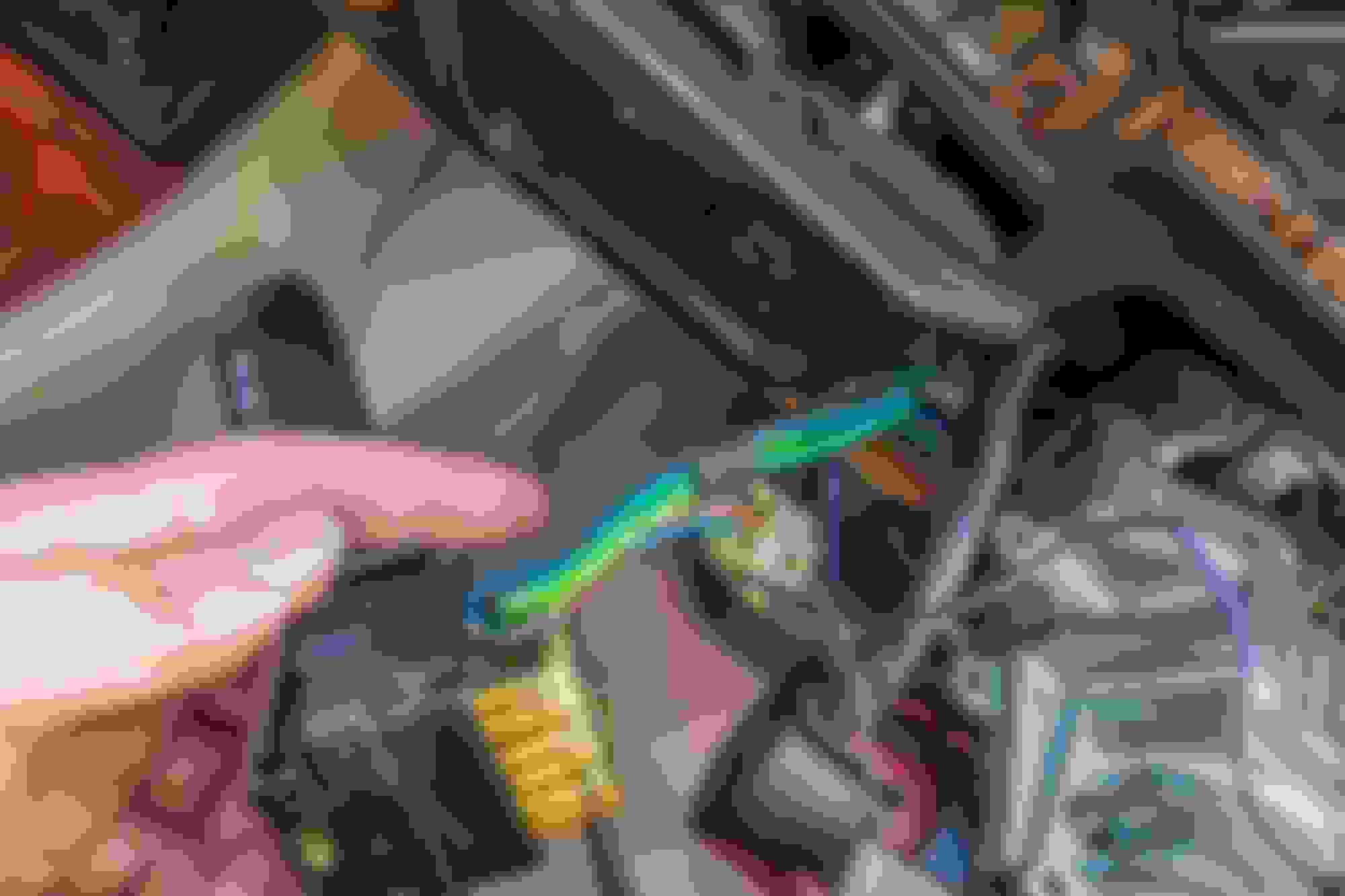
While I could find two brown wires, neither appeared to have a red stripe. There was a green wire with a red stripe, mind. But I didn't want to go randomly mucking things up, and wasn't sure how one would go about jumping the wire anyway. I had my multimeter with me, intending to use that, but I couldn't (a) identify the right wire, or (b) figure out where I would place one end of the probe.
What I did see, however, was what looks like an unattached plug. This looks very much like it's supposed to plug into something. The white one with female connectors arranged at random angles.
So I eased out the instrument panel, having remembered how to do that. I couldn't ease it out too far, and I didn't know how to pull off the sockets for the two wire bundles connected to the panel--and wasn't about to yank randomly. But I couldn't see anywhere obvious that this white socket would plug into. So I put everything back, which wasn't exactly a load of fun because, as I noted, I have the build and athletic prowess of the US President. But at least everything that did work before still works now, though there was a hairy moment when the right indicator dash light didn't go on, and instead there was an audible clunk, like something falling. But I tried it again and it was fine, and fine each subsequent time I tried (including hazards). So I might have screwed something up, but maybe not. Temporary glitch? Oh, and the car starts fine. I didn't terminally screw things up at least....
The next thing to check, I guess, is that relay at the front that Stuizzy mentioned. So how does one check a relay?
But if that's inconclusive, I'm taking her into my garage so they can feel queasy after lying head downwards trying to focus on something almost close enough to lick.
I've put the arrow at the wire you want. In the sidelight wiring diagram, next to the NR wire there is the notation CS2-3. There is a legend for all the diagrams, ( which I didn't include) that says what each connector is. In this case it says that connector CS2 is a 6 way Sumitomo Standard, in natural ( white) plastic. the -3 means that it is pin #3 for the NR wire. The black ground wire is called out as CS2-5.
I labelled the connector, so pin #1 is the upper right, the top row goes across to pin #3, and then pin 4 is the lower right, going across to pin 6, which is empty. Pins 1 and 4 are for the cruise set, pin 2 is brown/black ( visible in your second photo) and goes to the headlight relay. Pin 3 goes to the sidelight relay and the dimmer module, and pin 5 is ground. Somewhere on the connector, in very small writing the numbers will be moulded into the plastic. Sometimes they can be very hard to see, but they will be there.
I would have stuck my multimeter into the connector next to the ground wire and measured the resistance to a good ground - the metal steering column would work well, or the metal door handle. Ensure you had a circuit to ground. Then I would have run a jumper to pin 3 from ground and the sidelights should have come on.
No idea what the connector in your last photo is.
To test a relay: The pins should be numbered on the case. Standard numbers are 30, 85, 86, 87. Some have 87A in the center- ignore this pin. To test, connect pin 30 to the positive side of a 12V source. Connect the negative side to pin 87. You should have a very low resistance (under a ohm) between pins 85 and 86 and you should hear it click. Disconnect the power from either 30 or 87 and you should hear it click again and 85 and 86 should be open circuit.
Be aware that a relay can pass this test, but still not be functional. That is because the contacts get burnt from the arcing as they open and close while carrying power. The burnt portion can generate enough resistance that it can't flow meaningful amounts of power, yet can still conduct enough for the very small amount the multimeter will put through.
I have made something like a stretcher, it is at the height of the door sill and is a piece of plywood. That lets me lie flat on my back and look up under the dash in relative comfort without being a contortionist. It does make things like this easier.
Last edited by Jagboi64; Oct 10, 2020 at 10:23 PM.