When you click on links to various merchants on this site and make a purchase, this can result in this site earning a commission. Affiliate programs and affiliations include, but are not limited to, the eBay Partner Network.
Anyone know, what is, the correct installation orientation for Water Valve EAC4126?
This fits into the spigot, under the cap, of the filler tube of the coolant bypass pipe.
I can find no reference to this in the service literature.
Is the ball of the jiggle pin pointing towards the filler tube OR towards the air bleed banjo....top right of radiator?
Mine is towards the filler tube.....seems to me this is the wrong way round, for the design intent of the system...to stop "high pressure" coolant from entering the bypass pipe and hence not going through the radiator.
I've read in some posts that this does not even need to be installed .... probably true if the rest of the system is 100%, but this is likely to be of more importance depending on the amount of "plugging up" in the radiator.
I've tried searching the forums but no meaningful results.
Thanks,
Rob.
2006 X Type Wagon.
1994 XJS 6.0 V12 Convertible.
1987 XJ6 DD.
So,how does that stop "high pressure" coolant entering the "low pressure" bypass pipe and let the air out to the bleed pipe....this part of the system probably contributes around 1% to 2% to the effective cooling if working as designed. Of course the system is (air) pressurized so maybe that has something to do with the orientation of the water valve. I can actually convince myself that either orientation is correct!!!!
The little non-return valve should be placed so that water can flow FROM the crosspipe TO the radtop bleed pipe system. So if you insert it into the rubber pipe correctly, you should be able to blow through the pipe in this direction, and NOT be able to blow in the direction from the radtop to the crosspipe.
The idea is that water/air can bleed out of the crosspipe but not back into it. Having this crosspipe to radtop bleed system working properly is essential for proper cooling, the elimination of air pockets and efficient cooling system operation. There is a thread that explains it I shall try to find.
It is here: read down to my post explaining how the system works: https://www.jaguarforums.com/forum/x...system-142931/
Greg
Last edited by Greg in France; Sep 7, 2015 at 01:26 AM.
Thanks Greg, I had read your excellent post on the cooling system.....everything really falls into place once you start actually looking carefully at the "plumbing" on the engine.
That, is what prompted me to check out the water valve (with a view to cleaning it if necessary). I had performed exactly the test you mentioned....found exactly the opposite to your "blow" test....visual inspection prompted my post to determine the "factory" set orientation.....raising a slight suspicion that just
maybe this had been fitted wrongly at the factory, as car has 31,000 miles on it and non of this stuff looked disturbed.
Then reference Doug's post, stating that the one in his V12 was the same (incorrect it now appears) orientation as mine.....sooo........the mystery deepens.
This water valve seems really stuck in the filler pipe spigot....probably rusted in there.....anyone been able to remove one from the spigot while the bypass pipe is still installed on the engine?
I see that this water valve might have been intended to fit in the rubber tube (ref Grant in Oz).
Again, can find no service information on this.
Interestingly, I have a suspicion that the cooling performs better immediately after a good coolant bleed......so if the water valve is installed the wrong way,I wonder how long it takes before trapped air builds up in the system.
I just looked at mine again. The configuration would ALLOW flow *from* the small hose *into* the filler neck.
It would BLOCK flow from the filler neck into the small hose.
This is opposite of what you're saying it should be, if I understand you correctly.
Cheers
DD
Doug, precisely (opposite to the original design intent) the reason for my original post......installed the way it is now in my system, I feel it will seriously hinder the whole air bleed system.....which, presumably could only get worse with time and miles on the engine.
Then reference Doug's post, stating that the one in his V12 was the same (incorrect it now appears) orientation as mine.....sooo........the mystery deepens.
It *is* a bit of a mystery because it's isn't the type of thing that is normally fussed with....and therefore not likely to be removed and then reinstalled incorrectly.
It *is* a bit of a mystery because it's isn't the type of thing that is normally fussed with....and therefore not likely to be removed and then reinstalled incorrectly.
Cheers
DD
Yes, my initial thoughts, exactly, with reference to " not normally fussed with".
Thanks Grant, I've just looked at this again in my EPC with a 200% zoom and following exploded diagram conventions, it would seem that the "ball" does face the filler neck, of the bypass tube, as per what Doug and I have found.
So, either the parts diagram is correct and the whole theory of the air bleed system is "shot" OR it is shown ( and installed on mine and Doug's) incorrectly orientated.
The steel exit spout to which the rubber pipe attaches on the filler pipe corrodes and gets blocked. It is a very good idea to drill out/poke out any blockage so there is a decent sized free hole. I should have made it clear that I was talking about the 5.3 pre facelift HE, the later 6 litres may be different, but the JCP diagrams seem the same. Please accept humble apology if so.
On the 5.3 the non-return valve should fit into the special rubber hose, which OEM from Jaguar is silly money (20 UKP), and one end (the filler spout end) is wider than the other that goes to the radtop bleed pipe. The non return valve goes into this wide end.
As Grant so wisely says, NO valve is much better than the valve installed the wrong way round. The end the ball seems to be might be a misleading test, depending upon how the ball actually seals. Obviously any water/air MUST get out of the filler pipe if it is to be extracted by the radtop bleed system. If the rubber exit pipe to the radtop system has the valve installed incorrectly, the valve will prevent this happening.
I would suggest, therefore, putting the new valve into the pipe (still available and dirt cheap), blowing through the pipe from the filler pipe end. If you can, all is well. Check function by trying to blow through the other end. If after a nanosecond the valve pops shut, it is installed correctly.
Sadly, how it was installed at the factory is not an infallible guide to how it should be installed ! (true story: when Ford engineers started to get to grips with the V12 assembly line, they noticed that the endfloat measurer on the crankshaft installation section was not being used. They were told it was broken. When they looked at it, in fact the cable from the mains plug was too short to plug it in and it had NEVER been used).
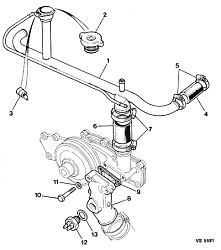
Anyway, the hose you need is no. 4 on this diagram
On the 5.3 the non-return valve should fit into the special rubber hose, which OEM from Jaguar is silly money (20 UKP), and one end (the filler spout end) is wider than the other that goes to the radtop bleed pipe. The non return valve goes into this wide end.
FWIW, on mine the valve is not in the rubber hose. It is in the nipple of the filler neck, as shown in the diagram posted by Grant.
Thanks for the pics etc guys. It seems I do not understand the idea behind the valve after all!
Can anyone cast any light on the theory behind the valve being as it is, and why there is a connection between the radtop airbleed system and the crosspipe at all, please?
Further to all the above, I re-read the Great Palm (page 180 in my edition) in the Air Purge System section:
"Onthe H.E., in addition to the ejector scheme, a �water valve� EAC4168 wasinstalled in the air purge connection to the bypass pipe. This is basically a check valve that allows air to flow out towards the header tank but won�t allow coolant to flow fromthe top of the radiator into the bypass pipe. This water valve is built into the fitting on the bypass pipeitself. "
This seems to me to indicate that the valve should let air out of the crosspipe filler spout into the radiator bleed system. The phrase "let air flow out towards the header tank" I read to mean "let air flow out of the filler spout into the rad top bleed system and thence to the header tank via the extractor" which seems to be confirmed by the last part of that sentence which reads: "but won�t allow coolant to flow from the top of the radiator into the bypass pipe."2
I am not saying Palm is correct, but I am saying it does seem to make sense to me, and I cannot see why there needs to be any flow back from the radtop to the crosspipe as when the crosspipe is activated by cold thermostats there are adequate connections without it (eg thermostat jiggle pins, other small extractor pipes, etc etc).Certainly, in my car's case, once the exit connection from the spout to the radtop bleed system was cleaned out and a new valve inserted letting air out to the bleed system, all air present in the fill spout disappeared and has never returned. How else is trapped air going to be removed from the fill spout? I am not saying, at all, that the Great Palm must be right about it, but I am asking what is the theoretical reason for the valve being the other way as it so clearly is in the above posts? Greg
Last edited by Greg in France; Sep 17, 2015 at 04:53 AM.
Thanks for the pics etc guys. It seems I do not understand the idea behind the valve after all!
Can anyone cast any light on the theory behind the valve being as it is, and why there is a connection between the radtop airbleed system and the crosspipe at all, please?
Greg
Very briefly my guess is that the designers wanted, or anticipated, air to accumulate in the pipes and bleed *into* the filler neck. But not the other way around. But why?
But that might not be exactly right or complete, either.
I've mildly mulled this matter since this thread started but haven't had time to seriously think about it. For one thing I've been searching thru my Jag manuals for that really good V12 coolant flow diagram. I know I saw it somewhere....years ago....but can't find it know. You probably know the one I'm talking about.