When you click on links to various merchants on this site and make a purchase, this can result in this site earning a commission. Affiliate programs and affiliations include, but are not limited to, the eBay Partner Network.
Ok, so I bought another radio hoping the backlight would work, but same problem. Does anybody know:
1. which wire powers the backlight so I can check for power?
2. fixed the backlight?
I am willing to be the guinea pig if no, but I would prefer it if someone had the answers already.
The LCD works fine, it just does not light up at night.
I have looked for places to repair it and have come up empty.
It's the early Harmon Karden head unit (with the sort-of multifunction button and the LCD on the right).
The power is "internal" so no separate fuse or anything like that. It's a small normal incandescent bulb with a blue rubber tiny condom on it.
The good news is that it can be replaced. The bad new is that it's not straightforward - the head unit has to be dismantled, including de-soldering the front panel from the metal frame.
I am just about to tackle this job - waiting for a rainy day and enough courage to get the soldering iron out. Will post pictures when I do if you can wait a week or so ??
If not ............... and this is from memory on one I did some time ago ............... remove head unit from car.
Remove "lid" from head unit.
Remove front panel assembly - two screws - one at each side.
Carefully pull front assembly away from head unit.
Remove volume / on off knob - pulls off
Remove plastic front panel complete with all buttons which will fall out all over the place.
Carefully unsolder the three (??) steel twisted mounting lugs that hold the PCB to the frame.
Untwist the mounting lugs with thin-nose pliers so that the PCB can be pulled away from the frame.
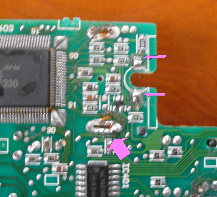
You can now see the small hole through which the bulb is inserted to provide the backlighting. You can also see the two small solder pads for the bulb.
Carefully unsolder the dud bulb - remove the blue condom - put old condom on new bulb.
Resolder bulb.
Reassemble head unit.
Have a large beer.
Last edited by DevonDavid; Aug 19, 2016 at 01:59 AM.
Reason: added information
Graham - Yes - have seen the forecast but unfortunately, a family christening (niece & twins & some distance away) must take precedence as far as this weekend is concerned !
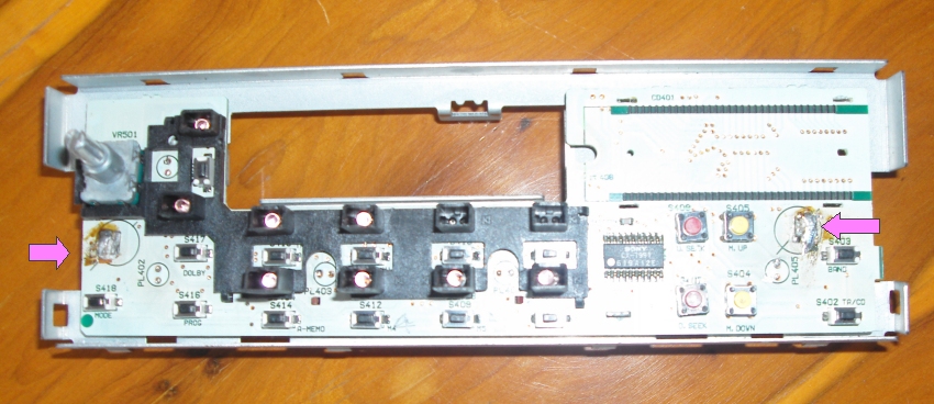
Dug this out of the "spares box" - I had originally hoped to replace the LCD but they are no longer obtainable so, it's not in the photographs. But - should give you an idea of where things are, the "lugs" that have to be unsoldered and twised, and the two pads for the tiny bulb which is then pushed through to the other side.
Cheers,
David.
Ok, as promised here are some pictures I took while doing the job- There are four steps:
1. Remove the front Fascia- two screws on the side, the lift to release tabs on the sides and then the bottom and top of the fascia.
2. Bend tab in the middle of the front PC board straight, then the two on the right and left (they must be unsoldered/desoldered)
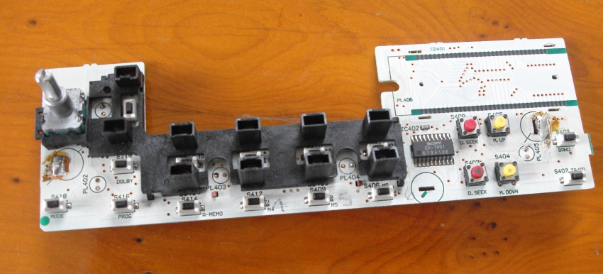
gently pry left and right side of PC board to remove. It is fastened only by the bent tabs, and is plugged into the radio pc board by pins. Easy peasy.
3. Unsolder light bulb and remove (both of mine the blue cover stayed in place) Then solder new one in.
Installation is the reverse of removal.
Difficulty if you have soldered before in your life- 3/10.
It was very slightly longer and thicker than the original bulb but seemed to work/look great on the test bench. It was slightly hard to get into the blue sleeve but only took 3 tries with the needle-nose pliers.
Unsoldering the tabs was actually harder than I expected, lot of solder and a noticeably higher melting point. I did not re-solder the tabs when putting it back together, just re-bent them.
My other bulbs were all still good so I did not do those.
Are you saying you can replace the bulbs behind the display without removing the LCD screen, as I'm currently changing all my interior bulbs to led.
My soldering skills are basic, but I've managed to do the j gate and switch pack. just need to sort out the radio.
I have the later Alpine unit, though i would presume in principal it's the same procedure.
I don�t know if it�s similar or not. On the HK units, you can remove the plastic face cover with a couple of screws and careful tab prying, then desolder & unbend 3 tabs to take the circuit board off the front of the radio and get access to both sides for soldering. Because I do not read much about lights on the Alpine units burning out, I assume they may be lit slightly differently...
Hi, some great pointers here to help fix the radio LCD illumination.
I removed my radio and air con console a while ago.
Some bulbs needed replacing on the air con unit and the radio was dead. All voltage feeds to the radio were fine.
I have recently bought a replacement AJ9600R radio for my MY97 XK8.
I have fitted it, to find out that the LCD illumination does not work. Everything else is good.
This is really annoying since the guy assured me in a text message that the display was working.
He is now no longer responding to my messages!
So either the bulb providing the illumination needs replacing or there is a problem with the feed to this bulb.
Annoyingly, I will have to strip the unit down to find out the problem.
Hopefully the instructions above will help me fix the problem.
In the meantime, I will keep chasing the seller for a response.......
Seller was great and understanding - gave me a part refund since I reckon I can fix the display myself - IF it's the bulb. Have just got to stage of removing blue condom......here goes.
Update: It took me a few months to get time to put the radio back in the car and for whatever reason this did not actually work. I could light the bulbs up fine testing with leads & a small battery but on the car the LCD screen was good but all of the other radio button backlights light up so dimly you cannot just con't see them anymore... I am stumped so I gave up and replaced the radio with a rebuilt one. I can't figure out how to delete my original post so I posted this follow up.
It was very slightly longer and thicker than the original bulb but seemed to work/look great on the test bench. It was slightly hard to get into the blue sleeve but only took 3 tries with the needle-nose pliers.
Unsoldering the tabs was actually harder than I expected, lot of solder and a noticeably higher melting point. I did not re-solder the tabs when putting it back together, just re-bent them.
My other bulbs were all still good so I did not do those.