When you click on links to various merchants on this site and make a purchase, this can result in this site earning a commission. Affiliate programs and affiliations include, but are not limited to, the eBay Partner Network.
Ooooh. That is the seamless upgrade I was looking at a while ago, and shied away when i saw the learning curve I had with integrating all the various bits and pieces and then the software setup. I ended up going the easy/uglier route and stuck a Joying head unit in mine.
Is that built with rpihat with openauto pro? I assume you have the controls mapped via gpio and then some 3d printing to mount the whole thing together. Did you tie it into the original amp/stereo, or bypass those to a new amp? Much coding involved?
It's all constructed from bits and pieces; individual off-the-shelf components as well as self-designed parts made from scratch.
Some more details:
This is using a Raspberry PI 4b 8gb computer board running BlueWave Studio's OpenAuto Pro head unit application. https://bluewavestudio.io/
OpenAuto Pro supports Android Auto natively via bluetooth, and optionally, Apple Carplay with the addition of a Carlinkit Carplay USB adapter dongle. I used the Carlinkit CCPA dongle which supports wired or wireless connection to the iphone. https://www.carlinkit.com/ccpa
The control knobs are my idea of a 'classic' control arrangement that aren't strictly necessary, but I thought they seemed fitting for the era of the car. They are rotary-encoder devices with momentary pushbutton, and interface to the system via GPIO ports on the Raspberry PI, and a custom transistor circuit for the power on/off feature.
This car has the Alpine Premium audio which has the audio power amp and CD changer in the boot. I've interfaced into those in this system, so it still plays CDs and retains full functionality of the car's original head unit including radio, cassette, and steering wheel controls.
Integration of this new 'infotainment' unit is accomplished with no alterations of the car's original wiring harness and no additional wiring running front to rear. It's plug and play, and fully reversible.
There are still some features that I had planned to add that are not yet functional or installed:
I had planned a reversing camera, which I've bench tested, but have not yet figured out how I will mount it. The additional components needed won't fit in the tiny space behind the dash display module, which is completely packed at this point.
Steering wheel controls are still only functional with the factory head unit. I need to find a place in the wiring to intercept those signal to share them with the new unit.
Power on/off currently requires manual intervention. I have to turn it on or off with the pushbutton on the unit separately from the car ignition switch. So it will need some additional circuitry to more seamlessly integrate that.
OpenAuto Pro supports 'virtual' gauges to display information from the car's OBDII system. Typically this would be interfaced through use of a bluetooth OBDII dongle. Haven't yet enable that or tested it.
Here's a view of the main assembly that includes the display, mount, electronics stack, and some interfacing cables, etc. The USB hub depicted was not used in my current installation, but it will be needed when adding reversing camera because the PI has run out of USB ports. New panel mount mimics the dimensions and design of the original nav module, but with new control set. PI board stack. Car harness connectors to the left. Car harness connectors plug straight into the original harness, but use of the wires is changed. Interconnections between the power management PI hat and my custom wiring adapter board.
The analog stereo L&R audio signals from the new head unit are transmitted to the amp in the boot over existing wires in the harness. The old nav display is a dumb RGB +sync interface that was driven by the the main unit in the boot via shielded cables in the harness. With the old display removed these wires are repurposed to carry the audio and video from the reversing camera.
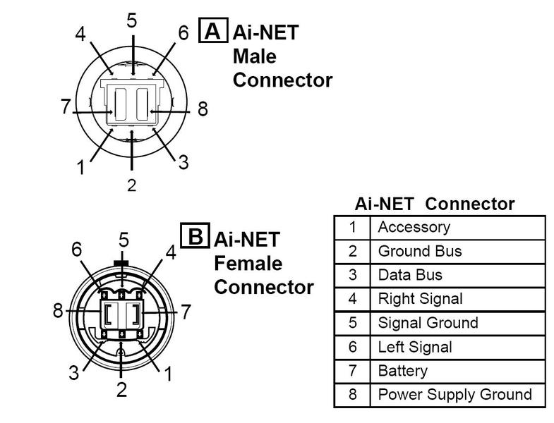
The factory audio system has no audio input jacks available to input an auxiliary signal. To make things more complicated, it sends audio and control signals to the amp via a secret proprietary Alpine "AiNET" bus.
In order to get the audio output from my OAP system into the power amp I would need to break into the AiNET bus and intercept the L&R audio channels, which are typical low-level stereo analog signals. But I also wanted to keep my CD changer and original radio operational. The CD changer has it's own AiNET input into the amp, but if you disconnect it the AiNET will not activate that audio channel because it needs to talk to the CD changer to confirm its presence.
My solution was to use a small signal DPDT relay to switch just the audio while leaving all the rest of the AiNET bus signals connected to the CD changer. The default mode of the relay connects the CD player audio to the amp. But when the OAP PI is turned on it switches the relay to route the OAP audio into the amp while leaving the CD player turned on and happy. I think it stays on even if there's no disk in the magazine.
This mounts in the boot and steals the CD player audio channel, but also steals the wiring harness from the navigation unit. The nav unit harness has three shielded cables used to transmit the RGB video signal plus one sync wire. I hijacked two of these to send the L&R audio, and the third to route the composite video from the camera forward to the dash. The sync wire was re-purposed as the relay on-off signal. The RCA jack is for the camera video.
Some signals from the harness were also forwarded on to the old nav unit to keep it happy because it's still participating in some of the AiNET communications for the radio head unit. The unique AiNET connectors are impossible to find by themselves, but I was able to cut up an available AiNET extension cable to reuse its connectors. All this is stuffed into another custom 3D printed box.
Thanks everyone for the compliments!
After a just a few days of driving with it it's made a remarkable difference in my enjoyment of the car, and I'm very pleased with the result. I've been working on this project for a few months now with a lot of technical research and lessons learned involved. I'll be happy to discuss the project further whether you are just curious or want to go down a similar road or even duplicate this.
Wow! You have taken roughly the approach I had envisaged when I looked at this, but I said to myself "I can't design in CAD so I'd need to learn that, I'm a bit rubbish at soldering, and I don't know how to cut into the stock aiNET so that's another hurdle to overcome, plus I don't like the OEM speaker setup anyway, and I have never touched the gpio features in rpi so i have to learn that too" and decided it was too much work for me. Apparently where I said "sod this, its too much effort" you said "Yes I CAN!" and made it happen. I have a reasonable idea of just how much just how much work, thought and iteration went into this and I am bloody impressed, from all the CAD work, circuit board soldering, etc. This is the nicest integration of android auto/carplay I've seen in the x100 because it completely retains the stock look and features and is totally reversible, versus hanging an android head unit screen out front. Also I see no reason this can't work with an aftermarket amp and speakers if one were so inclined. Im not a fan of the stock alpine/2ohm setup but each to their own.
I'm assuming for steering wheel controls you will need to intercept and switch with a relay the SWC signal on the harness going into the head unit behind the dash in a similar way to intercepting the left/right on the cd changer and reconciling the need to control the volume on the amp with the volume on the rpi will be challenging because you want some of the SWC signals to still go to the stock unit (I presume, vol up and down) with others (next/back) going to the rpi, but its all one wire so you'd need something to separate the signals out by resistance which significantly complicates things and may require code. Although you might not bother - the only ones I tend to use are vol up and down, everything else you can do with voice commands, so I can see why you didn't go there yet.
Other suggestions - your mic could be relocated into the stock mic location in the dome light/roof switches box, this is where I routed mine, just involves a bit of wiring and trim pulling.
For the reversing camera, however you integrate it I used this camera (or, a very similar one which is probably the same cos made-up chinese brands) which matches the rear "chrome" trim on the jag above the license plate and looks almost stock:
Really neat build and well executed. I'm also working on a similar RPI based solution but running my own java software instead of openauto, even though I have a copy of it and it sure gives bang for the buck. Hope to get the things in my Xkr within a few months
This was a nice build. I like it a lot. A couple of questions:
Did you 3-D print the bracket for the screen and pi and the rotary encoders that sits behind the wood veneer? If I wanted to get rid of the buttons and dials and instead use one of the 9.3 inch screens after taking a dremmel to the veneer to remove the bar of wood that separates the toggles and buttons from the screen, would that still work with the pi setup you came up with? Alternately, would it be possible to get the OE buttons to work with the Raspberry Pi?
Also, I didn't seem to catch how you are powering the Raspberry Pi and the LCD screen. What power source did you tap into?
Would bluetooth enabled dashcams and reversing cams be possible to install as a space saving alternative since as you say, it's already all cramped in there? Is it safe to leave the Raspberry Pi board exposed behind the veneer panel without a case?
@Throwback Quite right about the many iterations I went thorugh in the design process. Among other things I created a large pile of rejected front panel mounts in various materials and with small design adjustments. Not to mention the failed 3D pints that went straight to the bin. I probably have enough left over electrical components to make another just because I was buying multiples of everything in case I broke something. I'll post the 3D CAD models later to my grabcad.com account. Thanks for the tip on the camera - as it turns out that's virtually the same one I already obtained. Could you share details or photo of how you chose to mount yours?
Since I retained the factory amp, I still use the steering wheel controls for volume with the new system, and just leave the volume on full on the OAP side. It seems that the amp wants a rather strong signal level. I'd like to add the mode and 'next' steering wheel buttons to the OAP system though. I added an ADC converter to the PI, so it just needs to read the voltage level from the steering wheel buttons, which are just a set of resistors. The OpenAuto Pro app make it relatively easy to integrate this feature, as well as many other typical features, because the community has already worked though these and there's builtin support.
This was a nice build. I like it a lot. A couple of questions:
Did you 3-D print the bracket for the screen and pi and the rotary encoders that sits behind the wood veneer? If I wanted to get rid of the buttons and dials and instead use one of the 9.3 inch screens after taking a dremmel to the veneer to remove the bar of wood that separates the toggles and buttons from the screen, would that still work with the pi setup you came up with? Alternately, would it be possible to get the OE buttons to work with the Raspberry Pi?
Yes 3D printed. I'll post the CAD models later for anyone to modify as they wish. But I imagine cutting the 'wood' panel cover may not produce an attractive result. It's actually a very thin veneer of wood wrapped onto a hollow, stamped sheet metal backing - not solid wood. Cutting it will leave unsightly thin metal edges that would require you to make an external bezel that wraps over the edges to cover them up. It would be an entirely different look.
Also, I didn't seem to catch how you are powering the Raspberry Pi and the LCD screen. What power source did you tap into?
The Raspberry PI is powered by a Geekworm.com X710 PI hat board: https://wiki.geekworm.com/X710
This has a DC-DC converter that takes a 6V-36V DC input and outputs regulated 5V for the PI. It contains switching circuits that manage power-on and off for the PI. It's the board with the fan in my attached pictures. I've connected its power input directly to the car's 12V battery supply that comes in on the original nav module connector. When power is shut off it still maintains standby power to keep the RTC (clock) time which has very low current draw. But power to the PI is completely shut off.
Is it safe to leave the Raspberry Pi board exposed behind the veneer panel without a case?
I think it's safe enough. The cavity behind the panel is mostly self enclosed which forms a defacto enclosure for the PI boards. It was very clean in there when I took it apart, so I suspect not much dust or dirt should find its way in.
If/when I add more components they will likely have to be located elsewhere - either in the space over the factory radio head unit, or under the center console.
@Throwback Quite right about the many iterations I went thorugh in the design process. Among other things I created a large pile of rejected front panel mounts in various materials and with small design adjustments. Not to mention the failed 3D pints that went straight to the bin. I probably have enough left over electrical components to make another just because I was buying multiples of everything in case I broke something. I'll post the 3D CAD models later to my grabcad.com account. Thanks for the tip on the camera - as it turns out that's virtually the same one I already obtained. Could you share details or photo of how you chose to mount yours?
Since I retained the factory amp, I still use the steering wheel controls for volume with the new system, and just leave the volume on full on the OAP side. It seems that the amp wants a rather strong signal level. I'd like to add the mode and 'next' steering wheel buttons to the OAP system though. I added an ADC converter to the PI, so it just needs to read the voltage level from the steering wheel buttons, which are just a set of resistors. The OpenAuto Pro app make it relatively easy to integrate this feature, as well as many other typical features, because the community has already worked though these and there's builtin support.
Sure, here's the reversing camera in mine. Mounted directly beneath the trunk open button, drilled a small hole for the threaded post to go through then bolted from the other side. so technically not fully reversible, but its just a small hole and if you wanted to remove it for any reason you could just put a cap on it or whatnot. Had to remove some trim to get at the wiring loom. The wire then follows the trunk button wiring to the loom on the hinge - I was unable to fit the camera wire and its connector into the cable sleeve and housing that sits on the hinge so I just attached next to it, otherwise looks very clean and barely noticeable. It then follows the loom into the amp rack area where it meets the power/trigger wire tapped off one of the reversing lights, where I added a couple of runs of Cat 6 cable between the amp rack and the head unit in the cabin for passing signals through the very crowded cabin penetrations/grommets that emerge just under the soft top in the cabin. The cat6 cables I added then follow the cars wiring loom under the back seats, center console and up into the dash and bring the signal to where I have my joying head unit processor which is sitting in the OEM location behind the rough and ready blanking plate I made as I haven't got round to getting the one Monkeybrain designed and provided CAD files for printed. Would probably look better if I dyed it black instead of Oatmeal. I also need to paint the little bracket extension I made for my phone holder (I thought about just feeding the usb cable into the centre console storage and keeping the phone out of sight, but I find it handy being able to see both the phone and the screen. I daily drive this car so I went for practicality over looks) and I need to tuck that USB cable, but that's waiting for when I pull the center console to retrim it. I also include a photo of the reversing camera image for reference. Excuse the trash in the garage- my neighbor lets me use her spare garage for free so I can't complain (in fact, i am extremely grateful).
@Throwback Thanks. My 2000 has a different trim panel over the registration plate and no boot lid release button. Instead there's a recessed 'handgrip' area in the trim panel in that area, so no flat surface for mounting a camera. I'll probably 3D print a small adapter to fit into the recess.
This is an incredible build. I am absolutely excited to try and mimic your designs; it looks like a lot of care went into this.
I am very new to all of this and only just got my 2006 x100.
I did have one quick question that I don't think I saw above, did you use regular PLA for your 3D prints or some stronger type of printing material?
Hi, PLA should be avoided since it will not withstand cabin temperatures summertime, it will melt. ABS should be the preferred choice of filament for the print
I received some questions about kitting this and price, so I'm posting a parts list with links to the sources I purchased from and parts prices. I can't put together a kit at this time but it's something I might consider in the future. When putting together the bill of materials (BOM) I found that one power board I used has been discontinued, so I need to find a substitute for that. Also if I were to kit it I would want to have actual PC boards made where I used hand-wired prototyping boards.
My total cost (not including parts i ended up not using ) was about $450. That figure includes some things that could be cost reduced or optional - such as the Apple Carplay which Android users wouldn't need, which cost about $70.
Last edited by Geraldius; Mar 16, 2024 at 11:51 AM.


 ) was about $450. That figure includes some things that could be cost reduced or optional - such as the Apple Carplay which Android users wouldn't need, which cost about $70.