When you click on links to various merchants on this site and make a purchase, this can result in this site earning a commission. Affiliate programs and affiliations include, but are not limited to, the eBay Partner Network.
Over the years watching so much effort going into the replacement of front shock mounts, I get a feeling we are not happy with many of the answers, even the poly ones are starting to disintegrate in a short order.
The blame as I see it may be on the wrong end of shock and the material of the upper. A good bottom bushing is half the cost of a new shock, know why, it has to be made of a material that can withstand the weight of the car. A cheap one made of inferior rubber will not last as an effective part of the suspension system for any length of time. Just like the foam at the top. Let's look at the system and how these parts take the bulk of the force of the wheel up and down movement.
When you hit a imperfection in the road, not a pothole, just a little bounce, the first force after the rubber of the tire goes over to the bottom A frame assembly and that little rubber on the end of the shock takes a hit, ever before the shock starts into action. Next the shock starts absorbing some of the force as the springs go into action. Now as the push to reach the top of the shock tower force on the outside of the springs hits the foam at the top, that by the way have about as much absorbing power as a piece of wood to take the blunt force of the outer spring coils on the metal plate they ride on.
Welch came up with a good solution, for the top part, but alas, something went wrong with the process. The ones Jon89 did back in 2016 were very difficult to assemble, very difficult to crush or hold together with the pop rivets supplied. That did a great job and the center was a very hard cone shaped bushing and centered the shock.
New shocks in place gave us the bottom bushing on that job, but the thing about the job, after looking at the parts, I took the shocks and checked them and they had many miles left in them, but the bottom bushing in all were useless. You could wiggle them in a circle. They have a ball in the middle of that sleeve, and therein lies the issue. The hole for the bushing with a metal cover is slightly over 1 and 1/2 inches wide. The sleeve, without the middle knob is 15/16 inch, the metal surround at 1/16 inch all around takes up another 1/8 inch. What we have is 1/2 inch of hard rubber all around the sleeve that holes the bolts. That's not including the knob in the middle, which I didn't take the measurement of, but guessing it's another 1/8 inch up off the sleeve, or 1/4 inch right in the middle of the bushing. So what have we left, at best on the area not more than 1/2 inch all the way around the sleeve, 1/4 inch on each side, but wait a minute, the force will be going up on that bump and at best only half that or 1/4 of an inch along the sleeve to absorb the weight of that corner of the car.
Really good rubber compounds or it's newer composites don't have a chance to last very long and once that rubber wears the upward force takes even more toll on the foam at the top because as designed, half the protection built in has gone.
I'm looking into finding a solid bushing by Energy Suspension or someone with a thin sleeve to put the 12 MM bolt through. Surely it will stand a better chance than the original. A two piece would be ideal as it works on almost every application on the bug heavy muscle cars.
May take me awhile, but it's a good winter project.
Lots of folks will be interested in this project, Wayne. No question that a better lower shock bushing will help the upper shock mount to do its job better, and will likely lead to a longer lifespan for both components. I look forward to seeing what you are able to come up with....
Wayne, dont forget you can drill out the inner hole on those Energy suspension if needed. Hope that makes it easier to find ones with correct od and length.
Thanks John.
I have done that on my Spit6 and looked some more at measurements of what they build for other cars, takes forever.
So far, if I can have time to get the old sleeve out and turn off the bubble on the shaft, I will have good sleeve of 3/4 inch and in that case, I think I found the right one. A little larger on the poly but should compress in on the sleeve, if not, will trim it down in the drill press with some sand paper. I will have to cut the two half's down a bit, but easy enough.
They are Energy Suspension parts, just not sure on the red or black. I have used the red on TR6 A arms but the black looks a bit more dense, so still researching.
OH, the part number on the ES is 3.2125. Should be a perfect fit for the sleeve if it turns down OK.
I'll try this one more time, it showed posted but didn't.
Big surprise, the lower bushing in the shock is not anything like we think, it's a ball joint.
So the swivel around is by design and doesn't make it a bad bushing, any up or down motion would rule it bad.
It's really a ball riding in a neoprene surround, ball joint, and if it could move after the install position, could last a very long time.
When I started taking it apart, removing the outer seals, I wondered how it got so much grease in there, well, that is by design and the seals are like the ones on your ball joints. No rubber involved inside the seals, the restrictions on a new one are the seals, well maybe tighter on the connection between ball and neoprene surface. If your seals are good and no play up and down, you are good to go. We are replacing not only bushing on the bottom, shocks that have many miles left on them.
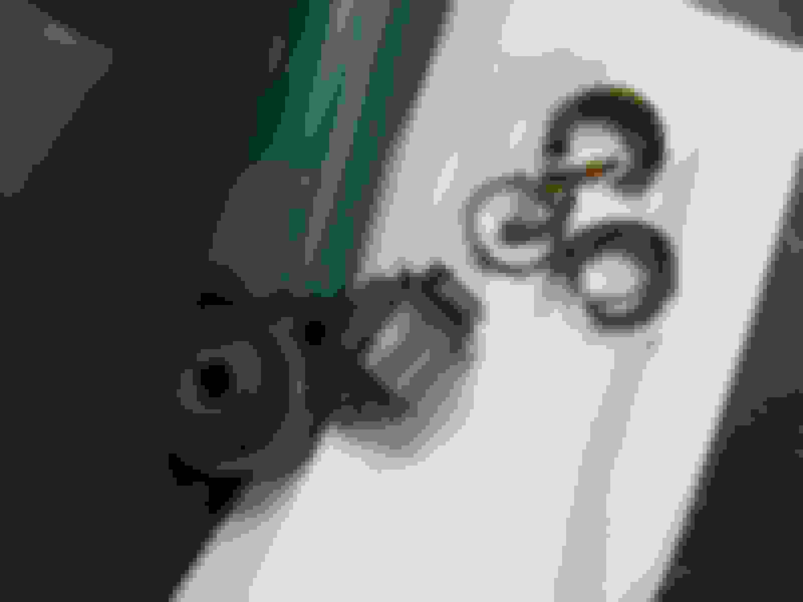
Some pictures to show, getting a straight shaft out of this one requires a bit of work.
Not sure rubber or poly would help take away all the force being applied to the top shock mount. How does is ride so well without flexible bushings?
I read the original post the other day and thought it was a bit off but had not had a chance to respond. Glad you got it clarified now.
The shock hydraulic does very little to absorb the impact of road surface changes. It does do the job of smoothing out the compression/extension to maintain stability and mask the changes to the driver. The spring itself is handling all the heavy work and is why the outer upper mount bushing bears the brunt of that load.
I think that the inner upper shock mount bushing gets trashed when the shock is collapsed abruptly from a road surface impact (pothole, etc.) and more energy ends up going thru that inner bushing than it can handle.
Regarding how it rides so well with a ball joint in the lower shock end. I think that the hydraulic operation of the shock is where the magic happens. The rubber bushing components are more like vibration isolators than impact absorbers.
I read the original post the other day and thought it was a bit off but had not had a chance to respond. Glad you got it clarified now.
The shock hydraulic does very little to absorb the impact of road surface changes. It does do the job of smoothing out the compression/extension to maintain stability and mask the changes to the driver. The spring itself is handling all the heavy work and is why the outer upper mount bushing bears the brunt of that load.
I think that the inner upper shock mount bushing gets trashed when the shock is collapsed abruptly from a road surface impact (pothole, etc.) and more energy ends up going thru that inner bushing than it can handle.
Regarding how it rides so well with a ball joint in the lower shock end. I think that the hydraulic operation of the shock is where the magic happens. The rubber bushing components are more like vibration isolators than impact absorbers.
Yes, interesting and complicated set of tradeoffs here. The springs are the central player in the suspension, and the shock is designed to damp the vibration so the springs don't feel or act 'bouncy'. But, the shock is generally a compression velocity dependent damper, so the higher the compression velocity of 'impact' the stiffer the damper. So, if you completely coupled the spring and the damper by putting a rigid plate on the top end without any elastomer intervening, there would be one hell of a stiff response to potholes, for example (high compression velocity, suspension essentially locks up). To reduce the effect of this this, one could design different velocity range responses in the damper. That's more complex and more expensive, especially active damping where you can change the compression velocity dependence over a wide range and it's difficult to completely get rid of the problem this way (the desire to have complex spring and dashpot/damper response for different things the car will encounter, for example braking in a very hard turn while hitting a pothole against normal driving).
So, they essentially put a viscoelastic spring/damper (the foam) on the end of the main spring and damper that also partially/incompletely decouples them and provides a small amount of damping/spring response. One could imagine a different design in which the center core and the outside annulus were optimized separately in the same configuration as the current shock mounts. Unfortunately, I also imagine this configuration destroying the interface pretty quickly from the enhanced displacement of one region vs the other. Then one could imagine some separated annulus vs center core in the shock mount, but one would no longer get the benefit of the side support of the other region which would increase the needed loading area for both the spring and the damper. and likely makes the failure issues more severe for one or the other.
So, the last, and probably best, solution for existing hardware might be to identify a tougher elastomeric material with the same viscoelastic properties to the current elastomer (i.e. reacts similarly in springiness and damping to the current foam across loading rates, loads, and overall displacements of the foam). There are plenty of new tough elastomeric materials in the last two decades, especially tailored composites, but it would be difficult to figure out which one would be best without knowing two things. 1. what is the force/rate/displacement response of the current mount over 2. the range of conditions considered. Theoretically, CATS cars may have sufficient sensoring to solve both problems if one or several could be logged over a long enough time. Perhaps not cost and time effective for most of us, including me, but might be fun for an Engineering Master's student design project combining electronics, materials characterization if we could locate the correct car or cars and I could figure out what the PIDs are for the sensors (mine don't have this, but this should be quick). If anyone is interested (and has the right car with newish mounts), I could see if I have any interested Master's candidates next semester. Perhaps steal one from mechanical engineering rather than biomedical engineering, my department.
Dale, thanks for a better technical explanation and I see you came to the same conclusion as I did. We need to just find the right material for the top mount, again. I say again, because I believe Welch had it really close years ago. Although a pain to install and would deter most for having a go. The centering cone was just a little too large but other than that, when you see Jon89's car, it did has done the job and function as it should.
Like you I have the feeling the material we are in search off, is already out there and I have been looking at sheets which are available. The good ones are expensive for just a try, so will look around for some buddies that may have some let over bits of one or the other. Do not mind if I have to buy a $200 or more sheet, as we could get 5 or 6 sets out of a 2X6 one.






 Shocks, the losing battle, maybe?