Jaguar Forums - Jaguar Enthusiasts Forum
  • LOG IN
  • REGISTER
  • Forums
    • General Jaguar Forums
      • New Member Area - Intro a MUST
      • Jaguar Forums Feedback & Suggestion Center
      • General Tech Help
    • Jaguar Models ( Current )
      • XF (X260)
      • F-Type ( X152 )
      • XE ( X760 )
      • E-Pace
      • F-Pace (X761) / C-X17
      • I-Pace EV
    • Jaguar Models ( Modern )
      • XF and XFR ( X250 )
      • XJ ( X351 )
      • X-Type ( X400 )
      • S-Type / S type R Supercharged V8 ( X200 )
      • XJ XJ6 / XJ8 / XJR ( X350 & X358 )
      • XJ XJ8 / XJR ( X308 )
      • XJ XJ12 ( X305 )
      • XJ XJ6 / XJR6 ( X300 )
      • XK8 / XKR ( X100 )
      • XK / XKR ( X150 )
    • Jaguar Models ( Classics )
      • Mark V - X 420G
      • MKI / MKII S type 240 340 & Daimler
      • XK120 XK140 XK150
      • E type ( XK-E )
      • XJ6 & XJ12 Series I, II & III
      • XJS ( X27 )
      • XJ40 ( XJ81 )
      • XKSS
      • XJ220
    • Other Jaguars
      • Other Jaguar Models / Concepts / Replicas
    • Diesel variants
      • Diesel variants - All models
    • Non Jaguar vehicles
      • Non-Jaguar Vehicles
    • Brand Review
      • Jaguar Press release
      • Jaguar Customer Relationship Centre
      • Jaguar Engines & transmissions
      • Wheels / Tires, Suspension & handling
      • Interior
      • Exterior
      • Audio/Visual Electronics
      • Detailing / Car care
      • Motorsports
    • Jaguar Classifieds
      • Marketplace
      • PRIVATE For Sale / Trade or Buy Classifieds
      • VENDOR 'For Sale' Classifieds
    • Regional
      • US Northeast
      • US Central
      • US Southwest
      • US Western
      • US Northwest
      • US Midwest
      • US Mid Atlantic
      • US Lower Atlantic
      • US Southern Midwest
      • Canada
      • Mexico, South America
      • UK & Eire
      • Europe
      • Australia - Queensland
      • Australia - New South Wales / ACT
      • Australia - Victoria / Tasmania
      • Australia - Western
      • Australia - South / NT
      • New Zealand
      • Other Areas
    • Official Site Sponsors
      • VENDOR Threads
    • General Interest / History
      • Sights N Sounds
      • Photography
      • Forum announcement archives / Forum History
      • Jaguarforums Merchandise
      • Memorial Section
  • News
  • Marketplace
    • Vendor Directory
    • Become a Vendor
    • Member Marketplace
    • Vendor Marketplace
    • Site Store
  • New Posts
  • Tools
    • Car Payment Calculator
    • Tire Rim Calculator
    • Vin Decoder
    • Recalls
    • Technical Service Bulletins (TSBs)
    • Members List
    • Live Feed
  • Gallery
  • View Dark Mode
    • Please register or login to enable Dark Mode.
  • Log In
  • Register
Jaguar Forums - Jaguar Enthusiasts Forum
    • Threads
      • Advanced
Dark Mode

Please register or login to enable Dark Mode.

Log In

Forgot your Password?

By logging into your account, you agree to our Terms of Use and Privacy Policy, and to the use of cookies as described therein.
or
 
  • Recent
  • Commented
  • Albums
  • My Pictures

My Post Pictures

Peter_of_Australia
August 13, 2022
 965
 0
Sort:
Most Recent
  • Default
  • Most Recent
SO THIS IS THE PROBLEM: CORROSION OF THOSE CONTACTS IN THAT HIDDEN CONNECTOR!!! CORROSION MEANS: NO ELECTRIC CONTACT = THE INFORMATION FROM THE SPEED SENSOR DOES NOT GET PASSED ON = ABS SYSTEM FAULT! How silly is it to have a connector there at all instead of having a cable going all the way thru. This is a design fault and a designed-in failure waiting to happen! After cleaning the corroded contact with contact cleaner, and a few minutes later forcing the surface contamination out with compress
0 2023/07/20 05:29:25 Peter_of_A
Somehow I managed to get that connector off. Using a heat gun, I then also managed to get that clip out of the "wall" (without heat gun, the clip would break), as I would not be able to slide the connector back on with the clip still attached to the wall (but I am getting ahead of myself - that is important later for re-assemlbly).
0 2023/07/20 05:29:21 Peter_of_A
That's the connector behind the wheel-liner. On the right is continues on to the speed sensor.
0 2023/07/20 05:29:17 Peter_of_A
0 2023/07/18 04:12:00 Peter_of_A
0 2023/07/18 04:11:55 Peter_of_A
Unit modified with Sony radio in X-Type
0 2023/07/17 05:24:08 Peter_of_A
OE unit in S-Type
OE unit in S-Type
0 2023/07/17 05:24:05 Peter_of_A
And that's the fire extinguisher mounted in the bracket.
0 2023/07/14 04:21:59 Peter_of_A
That's the bracket mounted onto that very solid metal X-bar. I removed the seat (after pulling the airbag-fuse (just in case)) to get better access.
0 2023/07/14 04:21:55 Peter_of_A
It's probably easier, if you take 2 and 3 apart first - but maybe it works like that as well: Transponder 1 goes into his "bed" as indicated. Add a bit of double sided sticky take or glue. Then turn over 6 and place it over 5 - there is only one correct way - one of the 4 "arms" is wider, and this arm goes into the widest gap. Next: Spring 5 goes underneath 5 and with the end that does not have the "spring-arm" sticking out. That spring-arm then goes exactly  into its "bed" in 2 as indicated. Th
It's probably easier, if you take 2 and 3 apart first - but maybe it works like that as well: Transponder 1 goes into his "bed" as indicated. Add a bit of double sided sticky take or glue. Then turn over 6 and place it over 5 - there is only one correct way - one of the 4 "arms" is wider, and this arm goes into the widest gap. Next: Spring 5 goes underneath 5 and with the end that does not have the "spring-arm" sticking out. That spring-arm then goes exactly into its "bed" in 2 as indicated. Th
0 2023/07/02 15:44:58 Peter_of_A
Page 1442 from the workshop manual pointing out the ATF check bolt
0 2023/06/26 06:05:08 Peter_of_A
0 2023/06/26 06:03:18 Peter_of_A
This is the fluid level plug! I have opened the correct one already a few times on 2 different X-Type, and also, you can confirm this on the X-Type workshop manual on page 1442.
0 2023/06/25 21:54:38 Peter_of_A
So after having bend back the 3 metal latches (No. 5s) and having made sure that the 4 No. 8 latches are free, the two halves are still stuck together, because there is kind of a strong bond at point No. 9. To overcome/loosen this, I pried in with a flathead screwdriver at the gap No. 10, using the screwdriver as lever between the plastic housing from the inside and the metal part underneath... And to get those two stubborn parts back together at reassembly, I used a pair of plumbers pliers to p
0 2023/06/21 19:08:47 Peter_of_A
0 2023/06/21 19:07:31 Peter_of_A
And this red cable goes to the interior door handle.
0 2023/06/21 05:01:29 Peter_of_A
Detail with metal rod. With the white bit pulled out, it is possible to re-insert the rod sideways, which makes re-inserting after mounting the mechanisms in the door already (with those 3 bolts) possible.
0 2023/06/21 05:01:27 Peter_of_A
Detail.
Detail.
0 2023/06/21 05:01:25 Peter_of_A
And luckily I figured this one out quickly when removing the mechanism from the car: the white part needs to be pulled out (using a very small screwdriver as aid, or even just with fingers) to release the metal rod, which connects to the outer door-latch.
0 2023/06/21 05:01:23 Peter_of_A
That is also a tricky one: If you want to take this connector off, the "latch" (No.6) needs to be bend back momentarily.
0 2023/06/21 05:01:21 Peter_of_A
This is the before mentioned microswitch.
0 2023/06/21 05:01:19 Peter_of_A
Detail of 2 of the 3 latches, which need to be bent to open the mechanism. Btw.: Opening the 3 bolds on the mechanism did not do anything for me.
0 2023/06/21 05:01:17 Peter_of_A
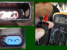
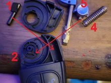
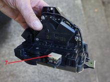
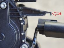
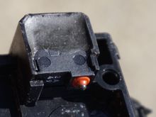
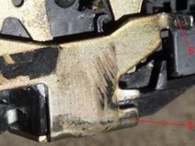
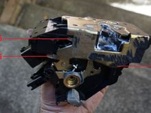
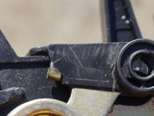
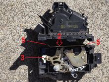
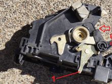
Here are the 3 metal latches, which need to be bend back before you can take the mechanism apart, if you want. Maybe you don't have to, if you manage to glue the new "rubber stop" into position without taking the mechanism apart. I actually had to take it apart twice, as I forgot the first time 'round to re-position the micro-switch, which hangs on the second connector (see below picture with No. 6). I also had that rubber removed, which is missing here in the picture and glued it then back on
0 2023/06/21 05:01:14 Peter_of_A
But this is the third position (3c), which should not have been possible as the plastic lever (which however broke off) would have restricted a turn of more than 90°. Thus, this is a position, which is "not possible" and the micro-switch "reads" an impossible situation, which would have confused the whole system! Hence those failures, where the remote would not open the passenger door... I needed to open the mechanism to be able to understand it. I found my own way to fix this. Obviously any att
0 2023/06/21 05:01:12 Peter_of_A
...and position 3b.
...and position 3b.
0 2023/06/21 05:01:10 Peter_of_A
So depending on if the door is open or closed, the are normally 2 positions possible: Position 3a...
0 2023/06/21 05:01:07 Peter_of_A
Detail of the broken plastic bit. Explanations to follow....
0 2023/06/21 05:01:04 Peter_of_A
Opening and closing the door leads to No. 1 moving No. 2 to the left and to the right. This again turn No. 3 90° to one direction and back. That was design intend. However, as a little bit of plastic, which would have restricted the 90° turn, had broken off (see last 2 pictures). No. 3 could now turn a bit more than 90°. No.3 "operates" the micro switch in the next picture, which is mounted on the other half of the mechanism.
0 2023/06/21 05:00:59 Peter_of_A
That the upper half removed from the base. There are plenty of clips and latches, which all want to be opened, but that would not suffice. 3 metal latches (No. 5s) need to be bent open. Note No. 1...: it sits in No. 2 (see next picture).
0 2023/06/21 05:00:54 Peter_of_A
Here you see the cowl re-installation-preparation with new double sided clear 3M double sided sticky tape. The cabin air filter is in this picture now yet back on.
0 2023/06/13 16:10:51 Peter_of_A
Here you see the utter mess, plus the remnants of the old double sided sticky tape in the windscreen.
0 2023/06/13 16:10:49 Peter_of_A
Note the damage the O2 spanner did already on the old O2 sensor. Had I tried any longer with the O2-spanner, I guess the hex would have been buggered beyond useabilty.
0 2023/05/30 05:06:13 Peter_of_A
Here are my old (broken and cut) O2 sensor and the replacement one.
0 2023/05/30 05:06:11 Peter_of_A
Thus, I grabbed the big gun(s): Proper socket and cut off the wires... I needed the hinged wrench, which allowed me to apply a big lever in an inward angle, as the master brake cylinder would be in the way otherwise. Oh, and I applied plenty of proper penetrant spray first. Btw.: Using a 22mm spanner was not possible, as there is a bolt holding the cat onto the exhaust-manifold, which is in the way and would prevent any turn with a spanner.
0 2023/05/30 04:50:37 Peter_of_A
First I tried with the O2 socket, but it kept slipping.
0 2023/05/30 04:50:34 Peter_of_A
0 2023/05/30 03:57:26 Peter_of_A
0 2023/05/30 03:57:23 Peter_of_A
And this is the base part of the gas-petal, which shows that there was no way to "pull it out" to free the carpet, as those 2 bolts were under the carpet. I unscrewed it after removing the carpet, because it was utterly rusty, and rust spreads like a cancer into neighbouring areas. I removed the rust and spray-painted it.
0 2023/05/29 06:03:48 Peter_of_A
After one day of drying in the sun. It will get another day of sun tomorrow.
0 2023/05/29 06:03:44 Peter_of_A
Detergent and a brush did the trick - and the water pressure cleaner.
0 2023/05/29 06:03:42 Peter_of_A
First
Page
12 of 25
Last
Go To
Page
  • 1
  • ...
  • 10
  • 11
  • 12
  • 13
  • 14
  • ...
  • 25
12 of 25
Go To GO
Go to page of 25 pages
  • 1
  • ...
  • 10
  • 11
  • 12
  • 13
  • 14
  • ...
  • 25

Top
Jaguar Forums - Jaguar Enthusiasts Forum
  • Contact Us
  • FAQ
  • Archive
  • Advertising
  • Cookie Policy
  • Privacy Statement
  • Terms of Service
  • Your Privacy Choices
  • Manage Preferences

© 2026 MH Sub I, LLC dba Internet Brands

Follow Us        


When you click on links to various merchants on this site and make a purchase, this can result in this site earning a commission. Affiliate programs and affiliations include, but are not limited to, the eBay Partner Network.