Jaguar Forums - Jaguar Enthusiasts Forum
  • LOG IN
  • REGISTER
  • Forums
    • General Jaguar Forums
      • New Member Area - Intro a MUST
      • Jaguar Forums Feedback & Suggestion Center
      • General Tech Help
    • Jaguar Models ( Current )
      • XF (X260)
      • F-Type ( X152 )
      • XE ( X760 )
      • E-Pace
      • F-Pace (X761) / C-X17
      • I-Pace EV
    • Jaguar Models ( Modern )
      • XF and XFR ( X250 )
      • XJ ( X351 )
      • X-Type ( X400 )
      • S-Type / S type R Supercharged V8 ( X200 )
      • XJ XJ6 / XJ8 / XJR ( X350 & X358 )
      • XJ XJ8 / XJR ( X308 )
      • XJ XJ12 ( X305 )
      • XJ XJ6 / XJR6 ( X300 )
      • XK8 / XKR ( X100 )
      • XK / XKR ( X150 )
    • Jaguar Models ( Classics )
      • Mark V - X 420G
      • MKI / MKII S type 240 340 & Daimler
      • XK120 XK140 XK150
      • E type ( XK-E )
      • XJ6 & XJ12 Series I, II & III
      • XJS ( X27 )
      • XJ40 ( XJ81 )
      • XKSS
      • XJ220
    • Other Jaguars
      • Other Jaguar Models / Concepts / Replicas
    • Diesel variants
      • Diesel variants - All models
    • Non Jaguar vehicles
      • Non-Jaguar Vehicles
    • Brand Review
      • Jaguar Press release
      • Jaguar Customer Relationship Centre
      • Jaguar Engines & transmissions
      • Wheels / Tires, Suspension & handling
      • Interior
      • Exterior
      • Audio/Visual Electronics
      • Detailing / Car care
      • Motorsports
    • Jaguar Classifieds
      • Marketplace
      • PRIVATE For Sale / Trade or Buy Classifieds
      • VENDOR 'For Sale' Classifieds
    • Regional
      • US Northeast
      • US Central
      • US Southwest
      • US Western
      • US Northwest
      • US Midwest
      • US Mid Atlantic
      • US Lower Atlantic
      • US Southern Midwest
      • Canada
      • Mexico, South America
      • UK & Eire
      • Europe
      • Australia - Queensland
      • Australia - New South Wales / ACT
      • Australia - Victoria / Tasmania
      • Australia - Western
      • Australia - South / NT
      • New Zealand
      • Other Areas
    • Official Site Sponsors
      • VENDOR Threads
    • General Interest / History
      • Sights N Sounds
      • Photography
      • Forum announcement archives / Forum History
      • Jaguarforums Merchandise
      • Memorial Section
  • News
  • Marketplace
    • Vendor Directory
    • Become a Vendor
    • Member Marketplace
    • Vendor Marketplace
    • Site Store
  • New Posts
  • Tools
    • Car Payment Calculator
    • Tire Rim Calculator
    • Vin Decoder
    • Recalls
    • Technical Service Bulletins (TSBs)
    • Members List
    • Live Feed
  • Gallery
  • View Dark Mode
    • Please register or login to enable Dark Mode.
  • Log In
  • Register
Jaguar Forums - Jaguar Enthusiasts Forum
    • Threads
      • Advanced
Dark Mode

Please register or login to enable Dark Mode.

Log In

Forgot your Password?

By logging into your account, you agree to our Terms of Use and Privacy Policy, and to the use of cookies as described therein.
or
 
  • Recent
  • Commented
  • Albums
  • My Pictures

My Post Pictures

Peter_of_Australia
August 13, 2022
 965
 0
Sort:
Most Recent
  • Default
  • Most Recent
I used 2 12VDC relays. The rted wire brings the 12VDC from the relay - FUSED!
0 2023/01/15 06:01:12 Peter_of_A
Next I need a power supply and an "ignition ON" signal. Well, the "switched thru" 12VDC from the ignition coil give me that signal (see above). In the past I then got myself an additional fused 12VDC feed directly from the battery, but that is actually too complicated. I just use those 12VDC from the coil as feed as well to power the LED DTRL.
0 2023/01/15 06:01:10 Peter_of_A
I found it and I spliced into the +12VDC cable, solder and shrink tube over it.
0 2023/01/15 06:01:08 Peter_of_A
DTRL is not allowed to be on (at least not in Australia), while the low beams (dipped lights) are switched on (it is suggested that this blinds other drivers at night - but which means as well, that it can be on with high beam...). SO I removed the low beam socket and measured, where the +12VDC are, when the low beam is switched on.
0 2023/01/15 06:01:06 Peter_of_A
...and the alternative would have been complete new LED fog-lights with integrated angel eyes. The thing is: I could not find them for the X308. I bought the one above for X-Type or S-Type and I was close to using it and simply "making it fit" (if it wants or not...  ;)  ). You can see I started already on adapter brackets. I definitely would have made it fit, but then I decided to use the other angel eyes...
...and the alternative would have been complete new LED fog-lights with integrated angel eyes. The thing is: I could not find them for the X308. I bought the one above for X-Type or S-Type and I was close to using it and simply "making it fit" (if it wants or not... ;) ). You can see I started already on adapter brackets. I definitely would have made it fit, but then I decided to use the other angel eyes...
0 2023/01/15 06:01:04 Peter_of_A
I bought it some time ago, probably on Aliexpress. This is a screenshot from such a listing. I chose diameter 80mm. Mine measures 82mm OD, according to this drawing even bigger. 80mm would have been best for the X308. I was torn about using those angel eyes here (above), added to the existing fog lights, and...
0 2023/01/15 06:01:02 Peter_of_A
That's the LED DTRL I added to my fog lights. It's a halo or angel eyes.
0 2023/01/15 06:01:00 Peter_of_A
...and two days ago ANGEL EYES...  ;)
...and two days ago ANGEL EYES... ;)
0 2023/01/14 00:26:35 Peter_of_A
I gave it chromed "wings" today, and...
0 2023/01/14 00:25:03 Peter_of_A
0 2023/01/11 06:48:56 Peter_of_A
ON the left side is the other cam-cover, which was not shown in the picture before: While that steel-wool-cover was still "just" hanging on, it was about to come off. So I had to fix both steel-wool-covers: After applying the silicone, I placed weight on it over night. Not beautiful, but functional, and no no one will see that later...
0 2023/01/09 03:38:15 Peter_of_A
Then used that high temp silicone to re-attach the steel-wool-cover. Small picture: Even two of the inserts (where the sparkplug-coil screw onto) simply came out - I put that also back into place with high temp silicone.
0 2023/01/09 03:38:13 Peter_of_A
I looked that the cam covers in more detail and noticed that there were basically cracks (as in picture above) on many places, and on both cam covers.I pre-drilled holes (tight fit for my old nails) and I applied high temp silicone, hammered them in and cut the remainder off (see cam cover in background).  Kind of "cross-stitch". Unsophisticated solution for unsophisticated material...
I looked that the cam covers in more detail and noticed that there were basically cracks (as in picture above) on many places, and on both cam covers.I pre-drilled holes (tight fit for my old nails) and I applied high temp silicone, hammered them in and cut the remainder off (see cam cover in background). Kind of "cross-stitch". Unsophisticated solution for unsophisticated material...
0 2023/01/09 03:38:10 Peter_of_A
When I removed the cam cover, I noticed that the platic lid came off the plastic cover, while the plastic cover was just lying around there on top of the camshafts and that "steel wool" was basically ready to fall out and do some serious damage - luckily, it help itself up there under the covers...
0 2023/01/09 03:38:07 Peter_of_A
aaa
aaa
0 2023/01/08 04:40:12 Peter_of_A
Assembled...
Assembled...
0 2023/01/08 04:05:24 Peter_of_A
I could have also put a new rubber underneath, but that one still looked alright, so I left it.
0 2023/01/08 04:05:22 Peter_of_A
Yes, this worked. New rubber on top.
0 2023/01/08 04:05:20 Peter_of_A
NOW THIS IS CRITICAL and difficult...: To get it right (refitting that huge washer back on, that is) it needs a lot of patience...: The trick is to make 100% sure that the washer is absolutely centred when it touches the "core". And this is very difficult, because the core is about 5mm below the top surface of the rubber. In preparation I took the assy above the other way round (without the washer) and pressed carefully until everything was a bit neater together. Then as you see it above, pressa
0 2023/01/08 04:05:18 Peter_of_A
Left: OE part from underneath - Middle: Modified new part with a slice cut off - right: new part, as it arrived.
0 2023/01/08 04:05:16 Peter_of_A
But that worked: I used that same small socket from the upper side and pushed that core thru to the effect that the huge top washer came loose.
0 2023/01/08 04:05:14 Peter_of_A
Now that does not work: I used a small socket and an hydraulic press - it looked like that core in there could be moved. But I figured soon, that this would not be possible from the underside, because the core is one part with the rim.
0 2023/01/08 04:05:12 Peter_of_A
Next I removed the 5 bolts: Lift-off! The rubber underneath does actually not look that bad at all - that is because it is heat-protected...
0 2023/01/08 04:05:09 Peter_of_A
I could not find a strong spanner small enough to hold the shock in position (so I took a big adjustable spanner, while I removed the nut with a size 17 spanner (I applied WD40 or similar before). NOthing will happen, when you remove that nut with the jack underneath as described.
0 2023/01/08 04:05:06 Peter_of_A
Before you remove all the bolts, jack up the car to the point just BEFORE the tyre would lift off. You can fine-adjust later as you need it. (Don't be confused that I start with the right top mount and I jack up the left side (the picture is from later, when I removed the left top mount...)
0 2023/01/08 04:05:05 Peter_of_A
That seems to be a standard sight... - I did not appreciate that...
0 2023/01/08 04:05:01 Peter_of_A
It was a bit though to fit the injectors into the fuel rail - I applied carefully a little bit of bearing-grease, so it slips in better. So with none of the clips for the injectors gone missing I fitted those first and then I carefully fitted the injectors back into the air intake - and mounted those 4 bolts on top of the rail again.
0 2023/01/05 03:24:26 Peter_of_A
These are the OE injectors: Left with new upper and lower gasket, right with old gaskets. I have not replaced the black middle gaskets...
0 2023/01/05 03:24:24 Peter_of_A
When I removed the injectors last time, I measured the OE gaskets and ordered accordingly. I found those on Aliexpress: Initially I measure on those thicker ones ID 8mm and CS 3.5mm. I ordered them already (material FKM) and then I spotted they someone is offering similar seal for exactly that purpose "fuel injector repair seals ID 7.8mm and CS 3.9mm - so I ordered 100 of those (AU$25). And the smaller seals I measured as OD 12mm and CS 2mm, and I ordered them in FKM (10 pcs for less then AU$4).
0 2023/01/05 03:24:22 Peter_of_A
But one injector just would not want to budge, so I removed instead the upper clip and pulled the rail off the injector - and only later pulled out the injector with great difficulty. Probably a bit to obvious to remind you not to loose any of those clips.
0 2023/01/05 03:24:20 Peter_of_A
I intended to also remove the other fuel line. This one was already last time more difficult to remove - and today it was - despite the proper fuel-disconnect-tool - even more difficult as with the upper throttle body in place, there was even less space. So I had to leave it connected and pull all the injectors off the rail with the rail not fully removed from the engine.
0 2023/01/05 03:24:19 Peter_of_A
So I pulled off the connectors again and pulled out the injectors again - I wiggled them out carefully.
0 2023/01/05 03:24:17 Peter_of_A
Also, the hex-head of that bolt was worn off or something - I assume it fitted an 8mm spanner once, but that was too big now and a 7mm spanner too big, this I had to sacrifice a 7mm spanner and transform it with a file into a 7.5mm spanner... That way I got it off. Also it was way too long - a real torture to get it off. I got myself a shorter M6x1mm bolt to suit a 10mm spanner (small picture).
0 2023/01/05 03:24:13 Peter_of_A
This means, removing the fuel rail from the air intake again. Meanwhile I also received the fuel line disconnector (light blue part) and I already disconnected one fuel line with it (the 2 ends are in the 2 red circles). And to free the fuel rail from the air intake, I also had to remove the bolt in the blue circle. This was really hard. Last time I had better access with the upper throttle body removed, but I did not want to remove it this time...
0 2023/01/05 03:24:10 Peter_of_A
You'll find all the required torque settings (e.g. air intake and throttle body) and torque-order via google.
0 2023/01/04 02:53:56 Peter_of_A
Word of warning: Think long and hard before attaching the upper throttle body! There are a lot of hoses, pipes and connectors, which want to be connected BEFORE you attach the upper half of the throttle body. It you don't keep that in mind, you will be quite busy detaching and attaching the upper half again and again.
0 2023/01/04 02:53:54 Peter_of_A
And the air intake got its 8 new gaskets.
0 2023/01/04 02:53:52 Peter_of_A
0 2023/01/04 02:53:50 Peter_of_A
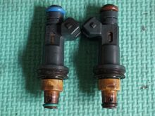
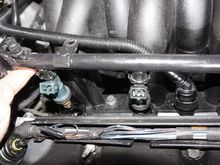
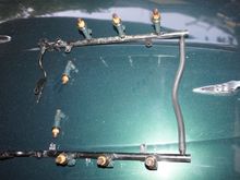
My initial approach of cleaning the injectors was to close those openings, which I did not want (e.g. with coins and heat-glue), then I put quite a bit of carby-cleaner (Carburetor-cleaner) into the rail, and while carefully applying airpressure (via air gun) into the rail, I attached 12V to the injectors (one after another). At 6 of the 8 the spray-pattern looked alright. I was a bit worried about the other two, which where highest up, when positioning the rail on the ground... - maybe it was o
0 2023/01/04 02:53:48 Peter_of_A
Alternatively, prefill the hose with carby-cleaner and apply carefully airpressue with 12V connected.
0 2023/01/04 02:53:47 Peter_of_A
First
Page
18 of 25
Last
Go To
Page
  • 1
  • ...
  • 16
  • 17
  • 18
  • 19
  • 20
  • ...
  • 25
18 of 25
Go To GO
Go to page of 25 pages
  • 1
  • ...
  • 16
  • 17
  • 18
  • 19
  • 20
  • ...
  • 25

Top
Jaguar Forums - Jaguar Enthusiasts Forum
  • Contact Us
  • FAQ
  • Archive
  • Advertising
  • Cookie Policy
  • Privacy Statement
  • Terms of Service
  • Your Privacy Choices
  • Manage Preferences

© 2026 MH Sub I, LLC dba Internet Brands

Follow Us        


When you click on links to various merchants on this site and make a purchase, this can result in this site earning a commission. Affiliate programs and affiliations include, but are not limited to, the eBay Partner Network.