
No crank. Ign Switch and Starter Relay voltage test results.
#1
 11-04-2013, 02:34 PM

New member. First post.
I searched this forum and got real close to having the answer, the question was asked but before it was answered, it was resolved by another discovery.
Here is where I am at.
Car has been great since I got it two years ago. The only codes it ever threw was for the wheel sensors for the speedo which has not worked since I got it.
Problem: Went to start it and no crank.
Things I�ve checked or done:
1. Battery charged and checked � OK. Battery charger was left on EXCEPT for when testing was conducted.
2. Both Megafuses - OK
3. PATS lights for a second then goes out.
4. Clear codes right away (probably should not have done that before pulling any codes. Currently the only code I get is P1000).
5. Ignition switch voltage check.
a. I have the Electrical Guide but my wire color/quantities do not exactly match the guide. I will reference the Harness Number and then list the Guide color and then my actual colors.
HN Guide Actual
FC18-5 WU WU
FC18-6 N WU and N
FC18-2 W RB
FC18-7 WG Y and W
FC18-1 WB WB
b. Voltage check results:
HN Key out Key In I II III
FC18-5 0 0 0 12.5 12.5
FC18-6 12.8 12.8 12.7 12.5 12.5
FC18-2 12.8 12.8 12.7 12.5 12.5
FC18-7 11.5 11.5 11.4 11.1 11.1
FC18-1 0 0 0 0 12.5
What I take from this is that the ignition switch is good because when the key is turned to start, FC18-1 is showing voltage.
5. Starter relay R20 voltage check: ISO numbers referenced. The number in parenthesis is the number referenced in the Guide. I think I have them cross-referenced correctly. Please verify this.
a. Key position II (run)
85 (1) From Ign Switch F1 � 0
86 (2) From ECM � 0
87 (5) To Starter � 0
30 (3) From BATT F27� 12.5
Key position III (start)
85 (1) � 0
86 (2) � 12.5
87 (5) � 0
30 (3) � 12.5
If I jump 30 to 87, the starter cranks (strong) but does not fire.
OK, here is where I lose it. Here are my assumptions:
1. No voltage at 30. Check components.
a. Ign Switch to F1 breaks into two circuits, goes to ECM and R20.
i. Fuse F1 � good but no voltage present at terminal.
ii. Voltage at PI1-6 at ECM: I have it exposed and took off the retainer clamp at the front of the unit but I didn�t pull it yet without further advice. Don�t want a programming charge if I shouldn�t pull the unit without due cause.
2. Since I see voltage at 86 when the key is turned to position III (start), the ECM is sending a Start Engine signal to the relay because the criteria has been met from the OK to Start signal from the instrument panel (neutral safety, generator warning) and other components such as PATS, TCM, inertia switch, etc.
Question: Should I see voltage at Primary Fuse Box fuse F1 when the key is turned to start? There are other fuses that are also not getting power that are nearby to that group but some of the other groups are getting power in the Primary Fuse Box. I can check each one for power if this is going to narrow it down.
The way I am reading the diagram is when the key is turned to start, power goes from the ignition switch to fuse F1, which sends voltage to R20-30 and to the Start Engine Request PI1-6 at the ECM. If I see voltage coming out from the ign switch to F1, but no voltage at F1, does this mean a open circuit in the wiring between the ign switch and F1, or are there other power feeds that I am overlooking?
I was looking for a TSB for my year, no crank troubleshooting procedure but only found one on X-Type.
Hope I provided enough info. Bare with the formatting, I couldn't space correctly. TIA. James
#2
11-04-2013, 02:42 PM
Veteran Member
Join Date: Nov 2006
Location: Glasgow, Scotland UK
Posts: 47,303
Received 9,005 Likes
on
4,113 Posts
#3
11-05-2013, 08:33 AM


Veteran Member
Looks a good battery voltage.
Usual problem is crank OK but no start so you're in the other category, sadly.
PATS appears happy.
Problem with starter motor / power to it?
There's a heft "no start" guide in the TSBs area I think (& probably on Gus's site jagrepair.com) but no idea how helpful it may be.
Make sure your car has no aftermarket wiring such as a hidden remote start (or had one removed! yes, it's happened to a member on here). This is unlikely but also tough to check but the nightmare of it... aargh.
#4
11-06-2013, 01:57 PM
Thanks for the replies. Here's what I have so far...
As I understand it, a relay works as follows:
30 � constant +
85 coil ground
86 coil power
87 switched +
87a powered by 30 through the relay when not energized
As it relates to the starter relay:
30 � Batt + F27 (Got juice, OK)
85 � ECM � (no path to ground in pos III, BAD)
86 � Ign Switch + (Got juice when key is turned to start position, OK)
87 � Starter + (Our Goal)
OK, now, The ECM is not providing a path to ground for the relay�s coil so the conditions have not been satisfied for the ECM to say �Start Engine�.
ID all conditions for OK to Start from ECM
� Generator Warning /Clutch Disengaged signal from the Inst Panel
PI1-123 � Inst Panel � at the ECM
PI1-124 � Inst Panel + at the ECM
� Neutral Safety Switch (NSS)
PI1-31 � NSS + at the ECM
Voltage test at switch:
NR � Power all the time
WG (Guide says GR) � power engaged; no power disengaged
� ?????
Questions:
1. What other conditions need to be met before the ECM grounds 85?
2. (Not the NSS argument) NSS - Is this a NO or NC circuit? Shouldn't the switch provide power when the clutch is disengaged? Since it is �working�, I�ll assume that the switch is NC, the ECM is looking for no voltage at PI1-31 when the clutch is depressed and the problem is NOT the NSS.
3. (Not the Ign Switch argument) Can the Ign Switch be ruled out because I see voltage at 86 when the key is turned to the start position? Fuse F1 at the primary fuse box sees voltage when the key is turned to the start position.
4. Can I pull the ECM to check for signals at the pins without any nasty repercussions? I want to check PI1-123, PI1-124 at the ECM connector.
5. Noticed that the rear window defroster is now not working also. Related? I�ll start checking this circuit for any commonality with the no crank problem.
This is getting challenging...
#5
11-07-2013, 01:12 PM
#7
11-07-2013, 01:25 PM
Veteran Member
Yes but they're about the most reliable part of the car so likely a waste of time unless it's just the harness you're checking.
Without its power the PCM will lose its learned values so will run a bit rough when reconnected till it relearns.
Just to emphasise: you're likely looking in the wrong place for the problem unless you believe it's had water ingress or some such incredibly rare event.
Without its power the PCM will lose its learned values so will run a bit rough when reconnected till it relearns.
Just to emphasise: you're likely looking in the wrong place for the problem unless you believe it's had water ingress or some such incredibly rare event.
Trending Topics
#8
11-07-2013, 01:47 PM
Alright guys, thanks.
police666: When I jump relay R20 term 30 to 87 the starter cranks strong but no start. If I pull the starter, will a bench test prove something out that sending the signal to the starter doesn't? term 85 is definitely not receiving a ground from the ECM so the problem is before the starter, right?
JagV8: I am trying to check the voltage for PI1-123 negative PI1-124 positive from the inst panel to the ECM at the ECM pins. There are no signs of water in this location. I don't suspect the ECM, just the components that are sending the signals to the ECM. I just want to pull the ECM to test at the plug then put the ECM back. Can I do this without reprogramming???
Right now, the only three conditions that I can see that needs to be met for the ECM to provide a ground to the relay is the NSS, the Ign Switch and the OK to Start signal from the inst panel. I think I have ruled out the NSS and the Ign Switch. I need to check the inst panel signal.
Thanks for the time on this, I appreciate it.
#9
11-07-2013, 02:15 PM
Veteran Member
The following users liked this post:
James Degenhart (11-07-2013)
#10
11-07-2013, 02:34 PM
#11
11-07-2013, 04:55 PM
Veteran Member
A bad power or more likely ground, maybe. Usually you get crank but no start and obvious fuel issue or a PATS flash code. Failing that you tend to get OBD codes. Bear in mind there are 10-20 modules but ordinary OBD tools will only read one so much useful data (if present) is only seen by OE tools.
#12
11-20-2013, 10:20 PM
Geez, there is a lot of activity on this site! Glad to be a part of it.
Just an update.
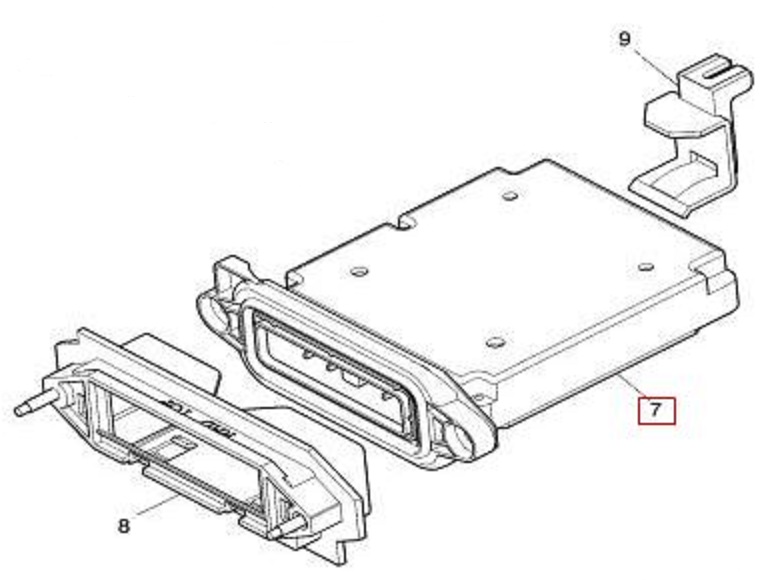
I removed the bracket holding the ECM. Tried to pull it out but no luck. There is probably some clip or catch that I am missing but I surrender, I guess I'm going to have to break down and send it to the dealer.
Thanks for the help, all.
James
Just an update.
I removed the bracket holding the ECM. Tried to pull it out but no luck. There is probably some clip or catch that I am missing but I surrender, I guess I'm going to have to break down and send it to the dealer.
Thanks for the help, all.
James
#13
11-21-2013, 03:26 AM
Veteran Member
#14
11-21-2013, 12:41 PM
Thanks for the words of encouragement.
I have prided myself over the years as being a DYI and have rarely sent any of my pets to the shop other than honing and boring cylinders, knurling valve guides and other machining and things of that nature. I have even surfaced my own warped heads on surface grinders and Bridgeport vertical knee mills and then inspected the surface with a CMM and profilometer. I have rebuilt auto trans, run my own gears out, assembled engines, fabricated, machined and welded mounts and brackets and chased electrical gremlins with success. I have designed and built automation machines from scratch, programmed PLC controllers, pick-and-place arms, virbratory bowls, vision systems, prox sensors, etc. and I am familiar with the nature of electronics.
Although I could of performed my recent clutch job, I did farm that out. I really like the challenge of fixing my vehicles but was pressed for time in that case.
I would like to continue to do my own work with the Jag although the complexity of the electronics in these Cats is challenging.
OK. One more swing:
There is a black sleeve that the ECM slides into. I can feel what seems to be a catch on the top of the sleeve, a square recess that I can feel with my finger. there is about a 5mm gap that I thought that when I depressed this that it would raise the catch to release the ECM. I tried to slide a plastic pry bar in to try to release the catch but to no avail.
Can you reveal the trick to release the catch? Is there a bolt(s) that retain it from the other side of the bulkhead/firewall? The retaining C-bracket is removed.
As it stands, the only other system that I have not checked is the PATS signal from the instrument cluster, although I don't think that is it because no error codes are being displayed through the security lamp on the top cowl. Sans that, I don't see any other requirements that the ECM needs to ground the coil at the starter relay other that PATS, ignition switch and neutral safety switch.
#15
11-27-2013, 12:49 PM
Alright, new approach.
After scouring through the electrical guide, I find diode D3 on the ignition coil relay circuit from the inertia switch and diode D4 on the ECM circuit, in the engine compartment fuse box.
I went to Advance Auto Parts, NAPA, a local dealer and a Euro "specialist", and they all could not provide me with a source for the replacement diodes.
The dealer wanted to put a whole new fuse box in to service this part.
Can anyone point me to a website to order theses diodes?
#16
11-28-2013, 06:04 PM

Member
Hey James,
I'm far from the expert, but I have found that the 'horses, not zebras' mindset has saved me some trouble a few times - and with that in mind:
- Have you checked the inertia switch?
- Can you hear the starter solenoid engaging? Maybe give it a love tap to make sure it's not sticking?
- Have you tried it with a different key, or the valet key to rule out the anti-theft system (despite the lack of PATS light) not liking a bad key?
The efforts you've described in an attempt to diagnose the issue makes me think that you probably have considered these already, but I figured it couldn't hurt to note them just in case.
Last edited by OxfordTheCat; 11-28-2013 at 06:19 PM.
#17
11-28-2013, 07:17 PM
Veteran Member
I am into this conversation late so if I bring up something that has been covered please forgive me.
Have you checked the starter relay? If not seated properly could cause a problem. I would also check the clutch pedal safety switch. The starter relay also sends power signal to the engine control module. I would also check The 15a fuse in the primary junction fuse box, it provides power to the engine control module for the crank engine request. All are critical to the start. Make sure you have not overlooked the obvious.
Link http://www.jagrepair.com/images/Auto...x2052003en.pdf Page 47, Fig 2.1
#18
11-28-2013, 07:28 PM

Veteran Member
#19
11-29-2013, 02:34 AM
Veteran Member
#20
11-29-2013, 08:27 AM
Veteran Member