When you click on links to various merchants on this site and make a purchase, this can result in this site earning a commission. Affiliate programs and affiliations include, but are not limited to, the eBay Partner Network.
I am re wiring my 69 4.2 Roadster.
I am stuck on the wiper switch, the original switch would not work the two speeds.
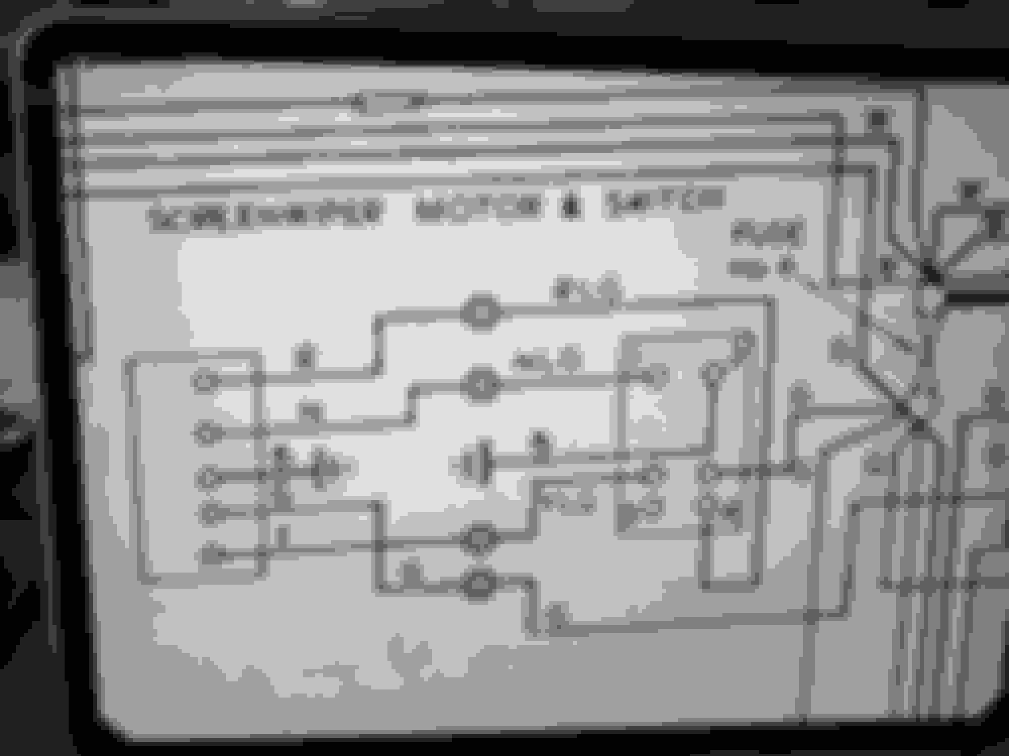
I have purchased a new switch SNG Barret, it has 6 numbered terminals, my handbook diagram identifies 4 but shows 5 been used. But the terminals they identify are not the ones they show to use. See attached diagram
if somebody can clarify this, they would have my undying gratitude.
Hi Terry,
I see what you mean, the diagram shows two unmarked terminals above terminals marked 3 and 4. I'll try to convey what I see in the diagram, but I hope I remember the legend for the wire colors.
On the switch terminal 1: N = brown wire from wiper motor connects to Brown/light green from switch.
Switch terminal 2 = black ground wire.
Switch terminal 3 = empty.
Switch terminal 4 = Red wire from wiper motor connects to Red/Light green.
Unmarked terminal directly above terminal 4 takes green wire from fuse #6.
Unmarked terminal directly above terminal 3 takes yellow/Light green connected to yellow from wiper motor.
If I misunderstood your question I apologize.
Good luck.
Bill.
Hi Terry,
Here is a link to an image I found on the net https://www.jagexp.com/phile/4/185/doc_4.JPG .
The image shows the wire colors and position, same as on the diagram you originally posted. This diagram too, shows the two middle positions without a reference number.
I hope this is helpful.
Bill.
I�m posting this for information only.
I recently re-wired my 1969 S2 Roadster.
It was an interesting winter doing it, rewarding as I now have wiring that is pretty standard and new. Anybody contemplating a similar project, feel free to contact me and I can share some insights.
One issue I did want to share, the wiper switch was in bad shape. I took the opportunity to replace it.
purchasing LUCAS 152 SA from SNG Barrett (C33862). I did post about this previously but without the resolution.
The switch has 8 terminals 1 to 8, every wiring diagram I have reviewed has this switch incorrectly shown.
Here is the wiring:
terminal 1 red/green
terminal 3 Blue/green
terminal 5 green
terminal 7 yellow/ green
blue/green and red/green wires are park, they close when switch is off
green and green/blue close when the switch is in the first detent
green and yellow/green close when in the full open detent
Hope this helps, I do have information on the internal and external wires from the motor if any body requires it.
Why Lucas would use different color wires out of the motor is beyond me.(there may be a multi car use that explains some of it)
Hi Terry,
Thanks for posting this information. I am sure it will be helpful to those that are or plan on replacing the switch or the wire harness. I am almost done with the complete harness and switch replacement. I suspect I will be referring back to this post when it is time to connect the wires to the switches. Thanks again for sharing.
Stay safe,
Bill.
The Hazard switch is also problematic, a little easier if you have an original switch the new ones are different.
I just used basic logic to sort it out. Do it with the switch out of the socket, it is much easier. Then replace it when you are confident it works. Just remember the Hazard and the indicating circuits are connected but only to the lamps, otherwise the are separate. Lucas used the hazard switch to supply power to the indicators, go figure!