When you click on links to various merchants on this site and make a purchase, this can result in this site earning a commission. Affiliate programs and affiliations include, but are not limited to, the eBay Partner Network.
Big thanks to everyone who helped me including TheRock, OzXFR and HolyFtype
I hope this write up helps someone else- obvious disclaimers apply- I'm an amateur mechanic so I may have made some mistakes, proceed at your own risk.
There are many reasons you might want to remove the supercharger in your Jaguar F-Type. Like me, you may have suffered a coolant pipe failure under the supercharger (a design fault), or you might need to replace the supercharger coupler. Or you might just be really bored and want to take your car apart. It happens, I understand you.
Resources:
The following threads on various forums were helpful in getting this project and this document over the line:
The supercharger sits on top of the engine block between the two cylinder heads. It has the intake manifolds bolted to its sides and the charger air cooler (intercooler) sitting on top of it. The large aluminium charge air cooler is what you see when you pop the plastic engine cover off.
The supercharger has the belt and air intake/throttle body at the front, and a number of electrical, fuel, vacuum and coolant lines attached to it at various places all of which need to be removed to get the supercharger out making this a moderately big job. Having said that, if you go slowly and take a lot of photos it is achievable for the average home mechanic.
Removal:
It helps to break the process down into a few steps;
1. Removal of the charge air cooler
2. Removal of attached hardware at the front of the engine
3. Removal of attached hardware at the back of the engine
4. Removal of supercharger drive belt and throttle body
5. Removal of supercharger
/Removal of charge air cooler/
The charge air cooler is attached to the top of the supercharger and intake manifolds with 22 bolts! Around the outside are 18 Torx 27 bolts (red and yellow circles) and in the middle are four 10mm standard bolts (green circles). It has two coolant hoses going into it on either side. On the front of the charge air cooler there is a stainless steel fuel line which is held in place with tabs attached to the cooler. It is possible to get the air cooler out without removing this fuel rail, however I subsequently found it impossible to manoeuvre the supercharger out with the fuel rail in place so I would recommend detaching the left hand side of this line and gently pulling it forward to make space. No fuel sprayed out of this when I removed it. The access is a bit tricky but can be done using a 17mm spanner.
There are also four tabs holding structures to the cooler which need to be removed (blue circles). At the front of the cooler there are two bolts which are very long (yellow circles)- these are quite seized and should be lightly greased with some antiseize compound when replaced.
On top of the cooler are 4 more standard hex head bolts (green circles) and an electrical plug. These need to be removed. The electrical plug has a little plastic tab which needs to be depressed to allow it to pull off. The coolant hoses at the sides also have two plastic tabs each- the trick with these connectors is to push them in a little first and then depress the two tabs and pull the connector free.
When all the bolts have been removed (and documented and stored in ziploc bags!), the air cooler can be encouraged to come loose with a few stern taps with a rubber mallet. The fuel rail can then be gently eased forward just enough to allow the air cooler to be manoeuvred out and placed in a safe place taking care of the gasket which is reusable. Put some rags in the intake manifolds to stop things falling into the heads.
/Removal of attached hardware at front of engine/
At the front there are:
1. Three electrical connectors (all on the same line that the connector of top of the air cooler was on)
2. two hoses going into the intake of the supercharger
3. the air intake t connector going into the front of the throttle body
4. a moulded plastic coolant connector with two big hoses from the radiator (right) and water pump thermostat (left) and small (brittle!) coolant overflow/expansion lines going back to the coolant tank. This pipe is called the upper water outlet pipe.
The electrical connectors all remove with small plastic tabs that need to be released. They are all different but fairly easy to work out.
The two hoses also have plastic tabs which need to be depressed to allow their removal.
The water (coolant) plastic connector needs to be removed. This is often called the upper water outlet. It takes the coolant from the large pipes from the radiator down into a down pipe into the block. This down pipe section is held in place with two torx bolts. When they have been removed the pipe can be levered gently up with a screw driver revealing a connector pipe with two o-rings. The actual plastic coolant connector doesn�t have to be removed completely to remove the supercharger, but it has been redesigned and replaced with part number AJ813917 so if you are doing this job to replace the lower water outlet �y connector� (the usual point of failure) you will need to replace this upper water outlet as well as it won�t work with the redesigned lower pipe
The thin coolant return pipe going from the back of the upper water outlet pipe back to the reservoir is very brittle and if it hasn�t cracked already it probably will when you start manipulating it. You can remove this pipe and replace it (part number # T2R5910)
When the water hoses and connectors are out of the way it�s easier to see the air intake. The large hose clamps on the throttle body and the left and right air intakes can be removed allowing the t- connector to be removed from the throttle body.
/Removal of attached hardware at the back of the engine/
At the back there are structures attached to the supercharger and on the left and right intake manifolds. Given the supercharger and manifolds need to come out as one piece, all of these structures need to be detached.
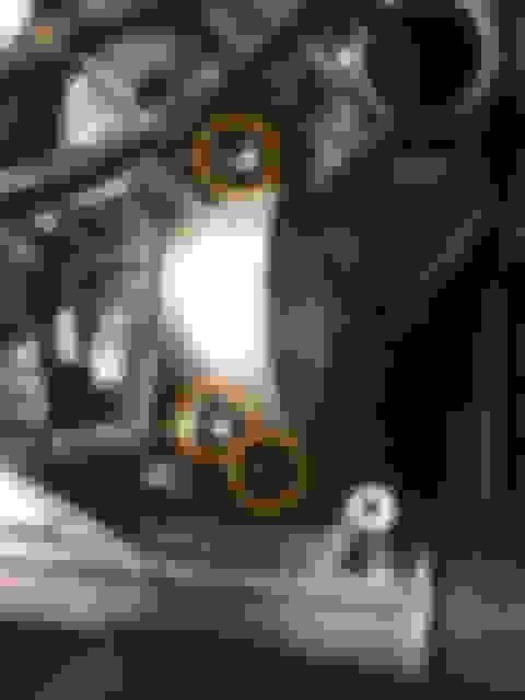
On the left there is an electrical connector (yellow circle) and a vacuum pipe (blue circle).
On the right there is a pipe with two screws holding it in place (red oval).
In the middle there is a complicated mess of components attached to the back of the supercharger. These include a lot of wires and the resonator pipe which pipes engine noise into the cabin (the �symposer�)
Completely removing all of this stuff would be pretty complex but it is all essentially held on the back of the SC with 3 torx screws as shown (turquoise circles). Before those can be access those 3 screws however you have to loosen some of the stuff on the top by removing the three bolts in pink circles. The outside two of these hold the bracket on and the middle one allows the symposer tube to be moved out of the way. The three screws can then be accessed (with difficulty) by using a long connector weaved through the tangle of pipes and wires. I should note here that actually accessing these screws without removing everything, whilst possible, is very fiddly and time consuming. Same goes for putting them back on during reassembly. Particularly the lower screw on the right hand side. This took me ages.
/Removal of SC drive belt and throttle body/
Before the SC can be removed, the drive belt on the SC pulley and the throttle body at the inlet of the SC need to be removed.
The drive belt tensioner for the belt is difficult to access from the top but it is possible. To access it the air intake pipes (both the t-pipe and the right hand intermediate pipe) need to be removed. Then a 3/8in drive ratchet or breaker bar can be slipped past the charge air cooler coolant lines into the tensioner. Pulling on the ratchet will put the belt on slack allowing the belt to be lifted off the SC pulley.
If all the above parts have been removed, the only thing holding the throttle body to the SC at this stage should be the 4 Torx bolts (1 at each corner- orange circles). When these are removed the throttle body can be moved forward off the supercharger with its rubber gasket. There are two pipes on the underside of the throttle body which can be left in place.
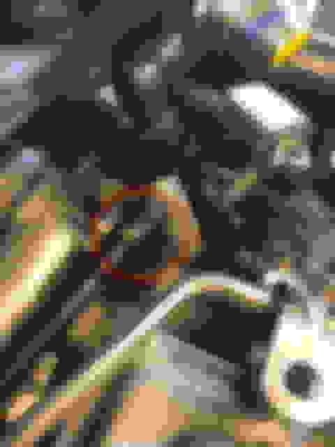
In the bottom of the intake manifolds are the 6 (3 on each side- purple circles) bolts that secure the intake manifolds/SC assembly to the heads. Once these are removed the SC should �lift out��.. but it won�t without some encouragement as it has two dowels (red circles) which are often pretty seized. Various techniques have been used to get the SC moving here- two people rocking on either side, various levers using timber and jacks but worked for me was a rubber tipped crowbar levering gently at a couple of points as shown. I used timber blocks to protect the surfaces. It didn�t take much force and once the SC was free it was easy to lift it out by myself.
As you lift the SC up you will notice there is a long hose going from the throttle body to the bulkhead which is attached to the underside of the SC with little clips at two points (yellow circles). Just pull these off.
Reassembly
As they say in the classics installation is a reversal of removal. However here are a few thoughts which might help;
* This CAN be done with one person (i did it) but lowering the SC into place would be easier with two people
* I replaced the intake manifold gaskets- they can only be installed one way and I cleaned all the surfaces thoroughly first. Gasket part number is C2Z17249
* The manual calls for �special tool� guide pins to be inserted into the cylinder head to guide the SC down into place on the gasket- these are just 50mmx M8x 1.25 headless bolts. I made some by cutting the heads of some headful ones.
* before you tap the SC down remember to clip the heater hose from the throttle body to the bulkhead back onto the underside of the SC
* If you�re ever planning on removing this again, remember how hard it was to get those guide dowels out of the block! I dressed mine with fine grit paper and applied copper antiseize before reassembly
* Some useful torque specs:
* the lower water outlet �y-pipe� 12 Nm
* intake manifold bolts: 25Nm
* Throttle body bolts 10Nm (if you want to replace the gasket it�s part # C2Z28265)
* Charge air cooler bolts 25Nm and a funky tightening order as shown!
That's one of the best, most comprehensive DIY guides I have ever seen for any kind of mechanical process, and is a huge resource for this community. Bravo!
Grwat right up. I pulled my SC today on my 2017 XF and it was a slight pain. The worse thing is the stuff bolted to the back of the SC. I had to pull it forward to remove tg he 3 torx screws holding the bracket on and that will be some trick wgen i put it back together. I might change the to hex head bolts so i can put a wrench on them. I still have to order parts as i want to get the SC off and make sure of what i need to order. Already changed the water pump several times and have that down to under 30 minutes.
Awesome write-up. One quick question. Will the engine run without supercharger installed. I know coolant would be an issue.. so insert by-pass tube in each. Throttle body would be disconnected.. Not looking for good performance, just wondering if I could spray some carb cleaner directly into intake.
Maybe run with just intercooler removed and spray carb cleaner into each cylinder (still with coolant bypass).
Thank you very much for the detailed guide! You saved my day (Or week).
My F-Type R broke down and was suddenly losing a lot of coolant. I thought it was the waterpump and that it's probably going to be a quick fix... Well yeah, it was also that damn Y-Pipe under the SC that split in half at the molding edge. Was a bit more of a hard job with the V8, especially the bolts on the rear.
I didn't see that you put in the Part Nr. for the Y-Pipe though. For anyone wondering, it's LR050935.
Greetings from Germany!
Excellent with good updates!
I have just one suggestion having also done this job, I'm pretty confident the supercharger oil fill volume is 85ml for the V6 and that was about the amount that I got out of mine too before refilling it. The 150ml you used/listed in the guide is the correct amount for the larger V8 supercharger,
Good to see you used the Eaton solid coupler replacement. I ended up using a different solid coupler though in principal it should perform similarly. Time will tell.
Fill volumes are hard to find for Jaguar application as there's no service guide, but the fill volumes I've been able to find for the Eaton TVS R1320 are between 120ml and 150ml (4.2oz - 5.2oz). I was confused by the loss of oil and a little skeptical about people pulling 70-90ml out then putting 120-150ml back, but some recent testing (https://www.jaguarforums.com/forum/x...esting-281383/) changed my mind and convinced me that a small amount of oil must be leaking over time. I'm sending my samples off for lab analysis next week to get readings on the metal solids and will update that thread with the results when I have them.
Thanks for the great write up, OP. I’ve used what you’ve posted to remove my F-Type’s supercharger and replace the supercharger coupler and oil.
When I removed the supercharger, I found a bit of corrosion/oxidation on the underside of the intercoolers and on some of the valve cover bolts. It looks like the insulating pads that sit between the intercoolers and the heads had been retaining moisture. Does anybody know if it’s necessary to retain the insulating pads? Does anybody know the part numbers for those pad? Mine are pretty crusty, and I don’t think my OCD will let me reuse them.
Thanks for taking the time to post this. It was very helpful when I serviced my supercharger and cooling system this month after it blew one of the seals on the water pump to oil cooler coupler. The V8 is virtually identical to the V6 with a few minor edits on the front and back of the supercharger. While I was at it, I dropped in new water pump, accessory and supercharger belt, an alloy rear water coupler and an alloy thermostat housing that I picked up from AliExpress and swapped out the electric fan (which I think may have been the original cause of the brief overheating). I also upgraded the supercharger cooling pump to the Bosch 0392022010. I changed the oil on the supercharger and removed the rear cover to check the gears (68K mile car). If you pull the back cover off the supercharger, you need an anaerobic sealant like Loctite 510 or 518 to make the new seal. Also, I use silicone lubricant from the plumbing dept at the local hardware store to lightly lube the new seals and hose barbs as it makes everything so much easier to put back together and the silicone grease doesn't harm the seals. The last piece of advice is to use a coolant vacuum kit when refilling the coolant. With the car back together and without any coolant in there, it is a great way to check that the cooling system will hold vacuum and check that the head gasket is still intact after an overheat. It is also a quick way to refill the cooling system and minimize any air locks.