When you click on links to various merchants on this site and make a purchase, this can result in this site earning a commission. Affiliate programs and affiliations include, but are not limited to, the eBay Partner Network.
Here's a little play-by-play for bringing a dead radiator cooling fan motor back to life on an early model S-Type. The 2003+ models use a different motor, so this is not applicable.
The symptoms of a failed cooling fan motor are very easy to spot. Your engine will overheat at low speed. Above 30MPH or so, forward motion will supply enough ram airflow through the radiator for adequate cooling, but the temperature will creep up at lower speeds. Your air conditioning will also stop cooling at lower speeds due to the lack of cooling airflow across the condenser. Do not continue driving the car with a failed cooling fan motor, as you risk VERY expensive engine damage.
This electric motor is manufactured by Gate, based in Hong Kong, a division of Johnson Electric:
Try as I might, I cannot find any aftermarket support for this particular motor. (Gate is not to be confused with Gates, a well-known US manufacturer of automotive products.) In a maddening twist from Jaguar, the motor is not available separately. You must purchase the entire shroud assembly, which includes the motor, fan blade, and shroud. The only part that wears out is the motor, but sorry, you have to spring for the whole thing. If you insist on new OEM, look for Jaguar #XR82853 and expect to pay upwards of $750! Here's one source:
Testing a fan before removal is easy enough. With the engine cool to avoid any risk of overheating, start the engine and turn on the air conditioning. Toggle down the selected temperature until LO is displayed. The air conditioning should kick on, and the fan will also be automatically commanded to run at the same time. Hold a rag in front of the grill. With the fan running, even at low speed, the rag should be drawn tightly against the grill. Do not run the engine for more than a minute or so, to prevent the possibility of overheating.
If the fan is not working, next step is to check the fuse. As Al Bundy would say, it's a Big 'Un. Under the hood, in the front power distribution box, you will see a single large 80A cartridge fuse. Remove it and check for continuity. If the fuse has blown, you could gamble on a new one and see what happens. But if it blows again, expect to find a problem with the fan motor. Don't keep throwing fuses at the problem:
If you have to replace the fan motor, access stinks. Expect a few scars by the time you�re done:
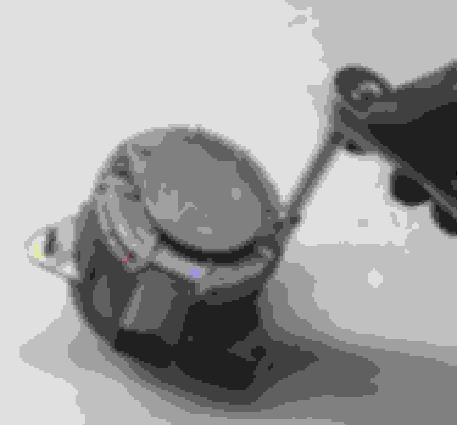
Before removal, you can check continuity through the motor windings to give you a general idea of the condition of the brushes. Here�s a view from the comfort of my workbench, but you can reach the connector with the fan still installed. A motor in good condition should read a fraction of an ohm through the brushes and heavy windings of the armature. I�m showing 53 ohms, way out of limits. Please note if you do see good continuity (less than 1 ohm), this is not conclusive that the motor is good. High resistance? Yep, that�s bad. Low resistance? That�s what you want to see, but it doesn�t guarantee there are no other faults with the motor. In my case, it was reassuring to see a bad reading before removal, so I knew the motor had to come out anyway:
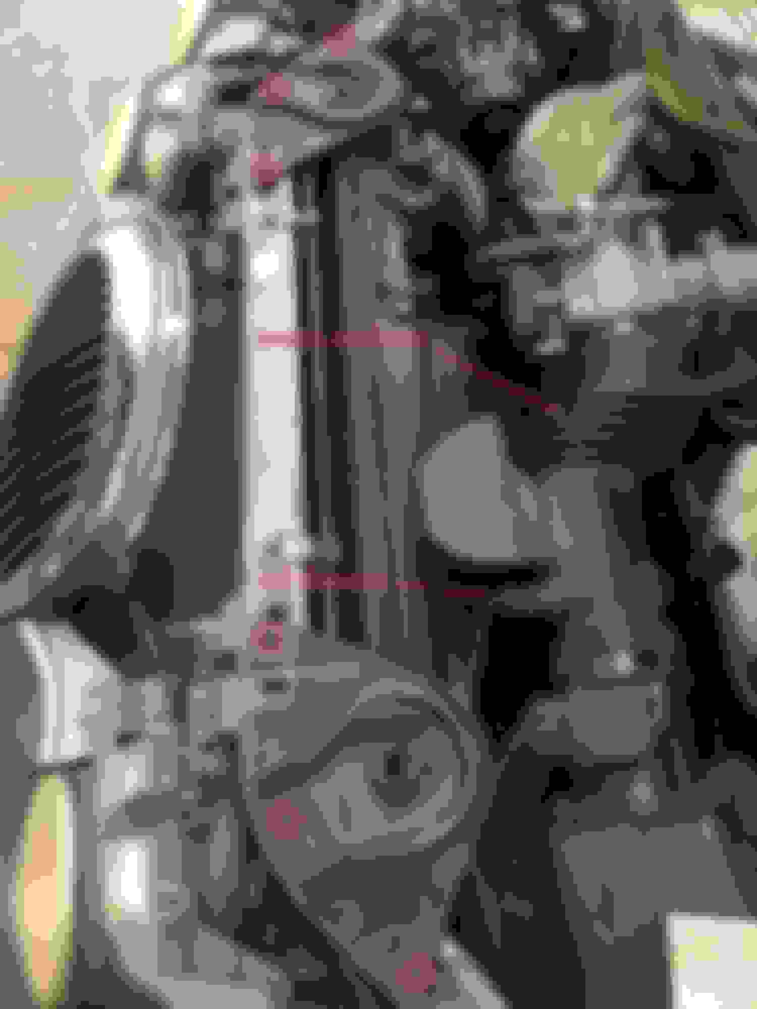
Disconnect the ground cable from the battery before any disassembly. Remove the trim piece across the top of the radiator. Once removed, you�ll see a pair of brackets, each secured by three bolts. They are shown below circled in red. Keep track of which side goes where, but if you lose track, they are marked underneath. Also disconnect the Intake Air Temperature (IAT) sensor and remove the intake air duct:
The factory service manual has you drain the coolant system and remove the radiator, but that is WAY too much work for me. Go ahead if you�d like, but I didn�t want to have to mess with servicing the transmission fluid level after dealing with the cooling lines. I didn�t even touch the cooling system. If so inclined, you could partially drain the system and remove the upper radiator hose, but once again, that�s too much work for me for very little gain. Regardless of whether you break into the cooling system, over at the US passenger�s side, remove the single bolt that secures the AC accumulator to the radiator shroud. Thanks to the flex lines, there�s enough play to swing the accumulator down and behind the upper radiator hose.
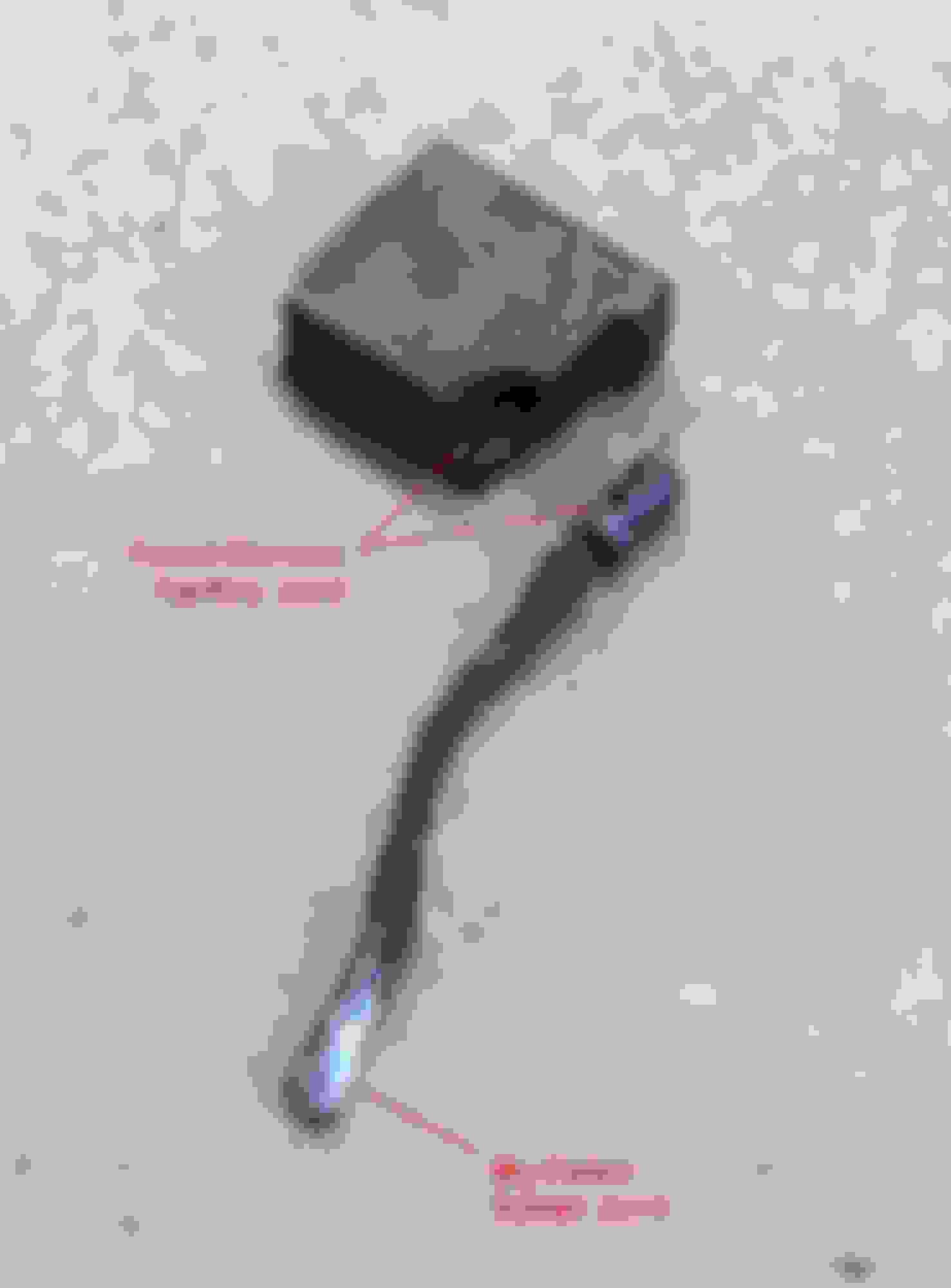
To give you an idea of what else must be disconnected, here�s the shroud sitting on my workbench. I�ve shown the location of the fan motor control module, but you don�t have to touch it during removal of the shroud. You�ve got four electrical connectors to disconnect. (You don�t need to disconnect the fifth connector at the fan motor just yet.) One connector is at the top, just inboard of the AC accumulator. You�ve got two more near the top at the other side. And then you�ve got the connector at the Dual Climate Control Valve (DCCV), down low near the accumulator, with very poor access.
These connectors use Ford�s infamous sliding red lock, which has to be released first. Here�s a quick video explaining the process:
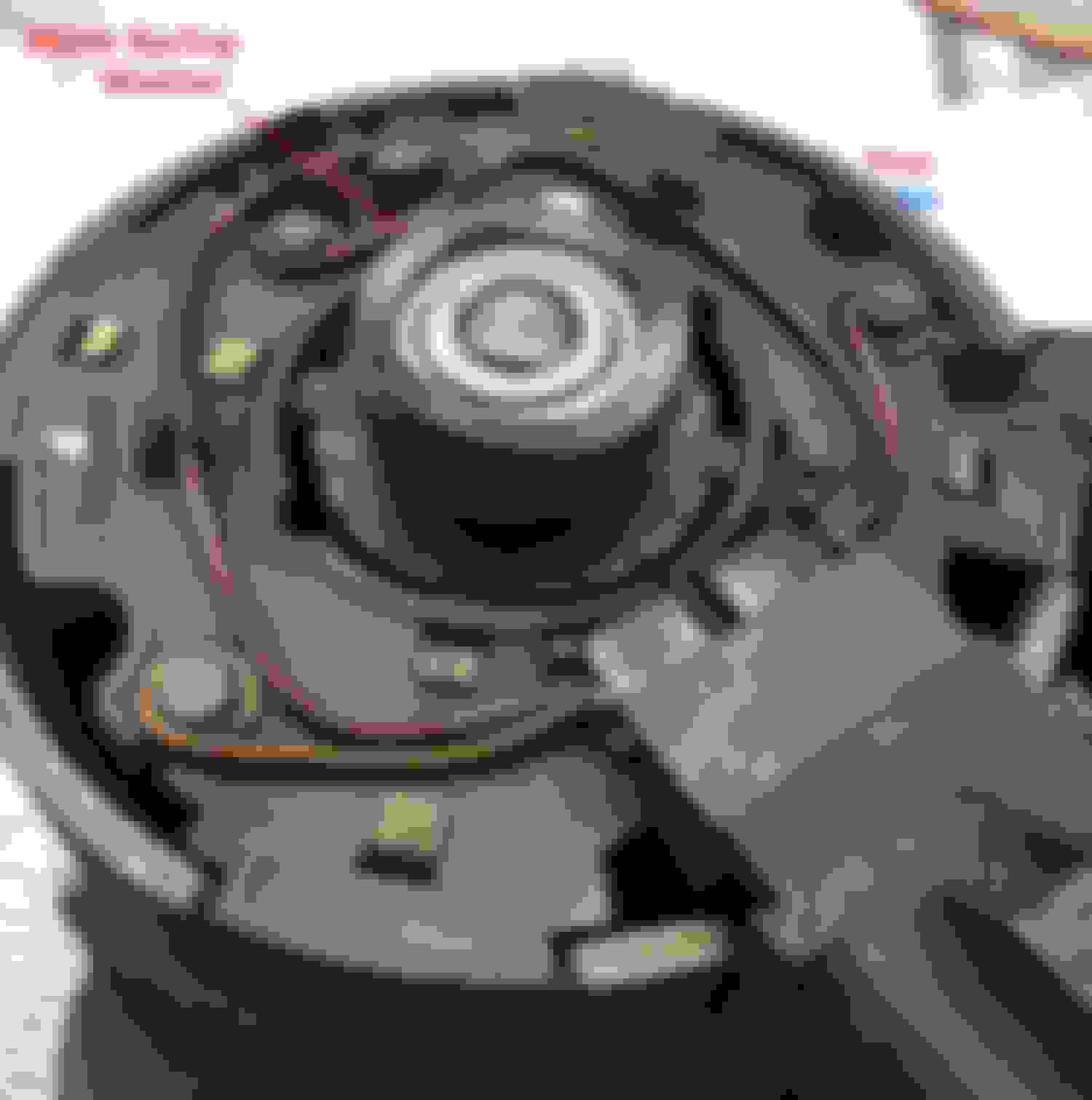
Here�s another view showing the control module and the cooling duct that surrounds it. Once again, you don�t have to touch this for removal of the shroud, but it�s good to know it�s there:
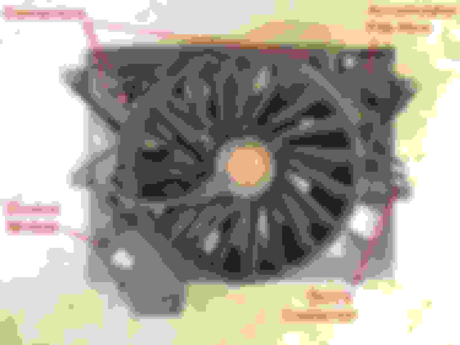
Here�s the forward side of the shroud, facing the radiator. Note the cooling duct for the control module at the bottom. It connects to a piece that stays with the car. This duct will separate easily during removal, but for installation, you�ll have to get underneath to align it. The bottom of the shroud has a protruding lip that wraps under the radiator and makes removal very difficult. Also, note the location of two miserable little clips. You�ll need to get on the ground, remove the belly pan under the radiator and pop off these two clips. In my over-inflated opinion, these two clips are not needed and I left them off during installation. Also note the pair of bolt holes near the top, and the protruding tabs on the sides. After removing the two bolts, you lift the shroud up about an inch to release the tabs. Sounds easy, huh? Yeah, except for the way the lip wraps underneath the radiator. You�ve got to tweak the shroud to free the bottom so it can move up to release the tabs. Even if you removed the shroud and radiator together, you�d still have to fight this lip. I�d love to meet the engineer who designed this. I used a thin piece of plywood on the aft face of the radiator to prevent any damage while trying to wrestle the shroud free. Also, I�ve highlighted the lefthand threads on the end of the motor shaft, which you must remember when it comes time to remove the fan:
Getting a bit ahead of ourselves, here�s a view with the shroud removed showing the aft face of the radiator. Note the slot where the tab fits, and the cooling duct at the very bottom:
As you wrestle the shroud free, you�re going to run into some interference with the throttle body. This is a staged shot during installation, but it gives you an idea what to expect. There is enough flex in the shroud to force the fan motor past the throttle body, but I have a better idea if I ever have to do this again. One option is to remove the throttle body for better clearance. Another thought is to remove the three fasteners that secure the motor to the shroud. Back up a second, and you should first remove the fan blade from the shaft (remember those lefthand threads!). I need a guinea pig to try this, but I think removal would be a lot easier if you removed the fan blade and unfastened the motor from the shroud. No promises, but it�s worth a try. Don�t forget to unplug the connector from the motor if you�re going to try it:
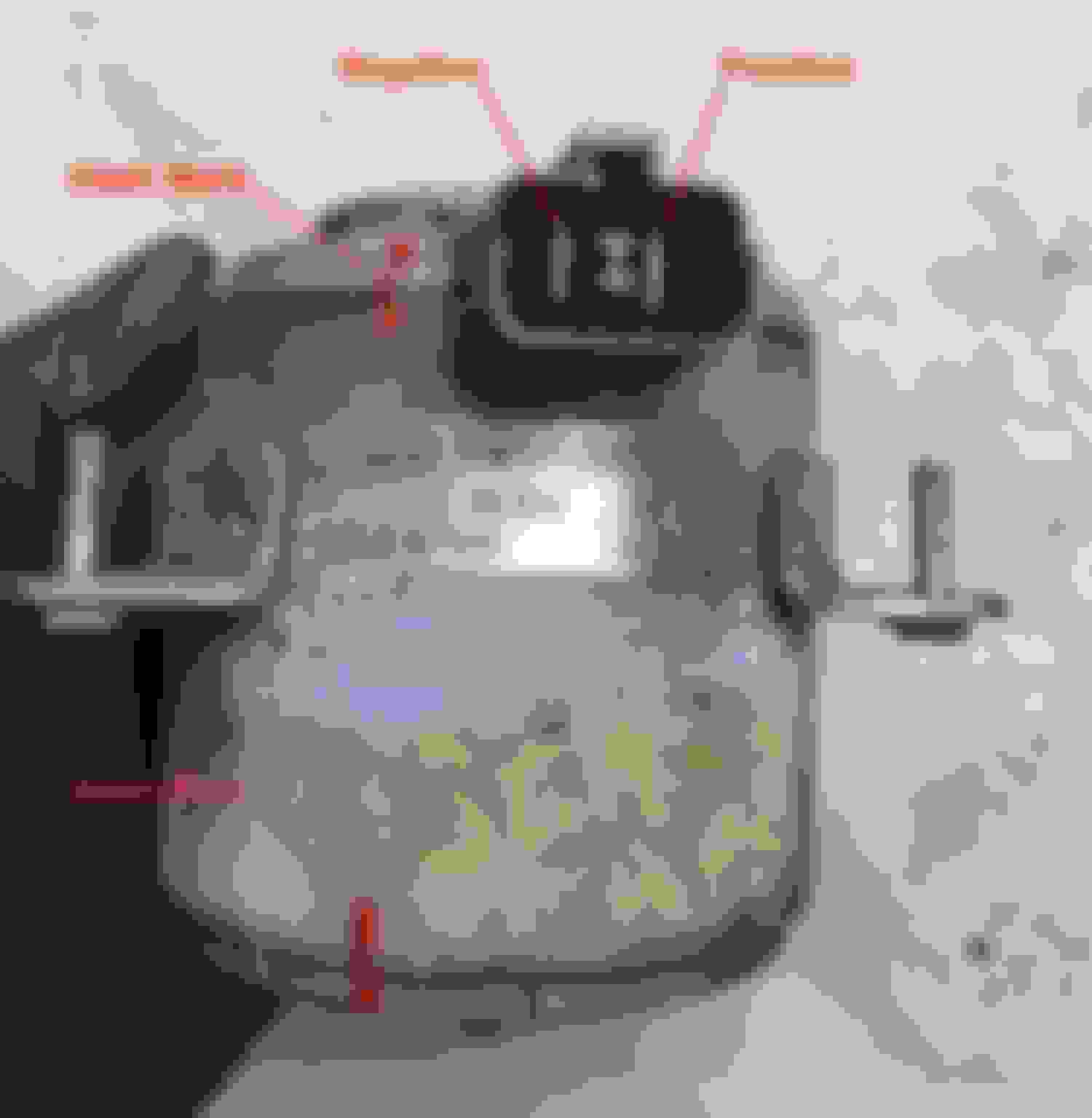
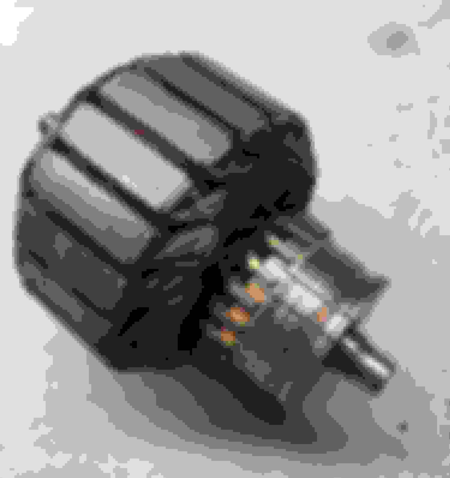
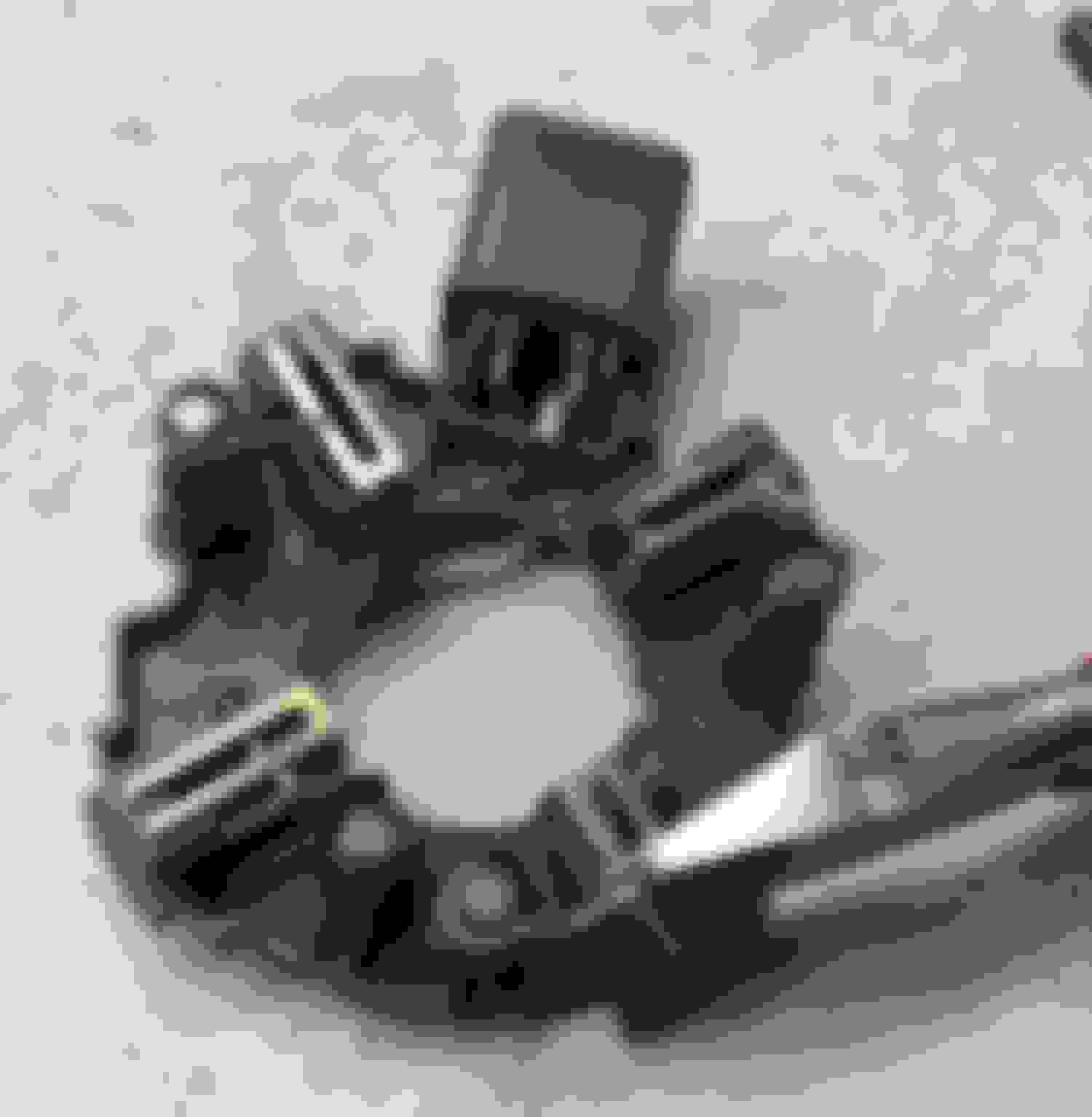
Once you get the shroud and/or motor free, apply some antibiotic ointment to the fresh wounds on your arms. Here�s the motor removed from the shroud. Note the Gate part number 9010695, which doesn�t seem to cross to anything. (I�m only showing it to irritate you and give false hope the number might mean something.) The arrow shows the direction of normal rotation, and I�ve labeled the two terminals for testing. Use a marker or paint pen to make hash marks for alignment during reassembly:
I must warn you. It is VERY messy to work on these motors. Expect LOTS of black dust from the brushes as they wear down. Disassemble the motor on newspaper or other disposable surface. Don�t blow it out with compressed air or you will create a nasty black cloud that will follow you for months. I didn�t want to foul my shop vacuum with this stuff, either. Just tap the motor on your disposable work surface to knock the debris loose. Two through bolts secure the two ends to the core:
Here�s a disassembled view of the brush end of the motor. Note the wave spring washer which fits between the bearing and the end cover. Don�t lose it:
Next step is to carefully remove the brush holder and flip it over. The four brushes will pop loose, but don�t let that alarm you. Note the unrealistically clean work surface in this shot. In practice, you will feel like a coal miner:
Be VERY careful removing the armature from the motor body. The magnets inside the body are incredibly strong. Don�t get your fingers caught between the armature and the magnets. I do not care to discuss how I know this.
At the drive end of the motor (opposite the brushes), the end plate slips off easily. The bore of this bearing is a slip fit on the shaft. For reasons unknown, this bearing is swaged into the end plate. If the bearings are worn, you�ll need to grind off the swage for replacement. There�s no need to swage the new bearing in place, nor any way to do so. I have no idea why the manufacturer went with such overkill. Also note the squared-off cross section of the shaft where the fan blade fits:
At the commutator end, you will need a small bearing puller. Even if the bearing is still good, it will have to be removed for something to grip while cleaning up the commutator. The opposite end of the shaft, seen above, does not have a round cross-section and cannot be gripped in a conventional 3-jaw chuck:
To inspect the bearings, I recommend trying to spin them while the motor is disassembled. If you try to spin the armature by hand with everything assembled, those killer strong magnets keep the armature from spinning freely. You could end up thinking that perfectly good bearings had failed. The OEM bearings were SKF brand, #6200-2Z/C3WT. Any good bearing supply house can supply an equivalent replacement based on that number.
After removing the bearing next to the commutator, chuck the armature in a drill press or lathe. This is why you must remove the bearing, because otherwise there is no way to grip the armature shaft. In this picture, note how I�ve brought the table up close from underneath. The other end of the shaft is protruding through the hole in the table, just in case the armature works loose from the chuck. With the spindle spinning at a low speed, I carefully cleaned up the commutator with a file:
Next, you will need to clean up the grooves between the commutator segments. I�ve made a special thin hook from a piece of hacksaw blade:
Here I�m removing any conductive debris between the commutator segments. Then use the hook to lightly chamfer the edges:
With the commutator all clean and spiffy, install the bearing. I�m using a socket to press against the bearing�s inner race. Note the nut installed at the other end to protect the shaft threads:
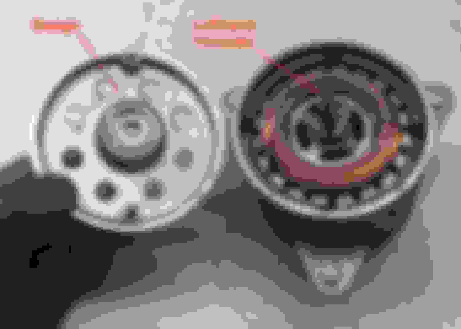
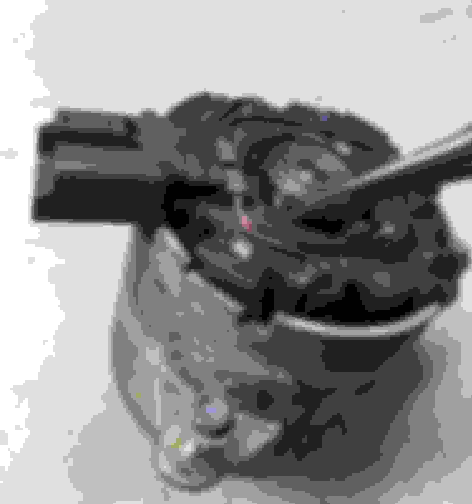
With the armature ready to go, this is probably as good a point as any to mention my history with these motors. About 5 years ago, the (original?) fan motor failed in my �02 V6. I removed the motor and found severe internal damage. Check out this heat damage (melted plastic) on the big connector at the brush holder:
During a tear down, I found two of the four brushes completely worn away. One of the springs wrapped around the commutator and wore a nasty groove into it. This armature is obviously scrap. I�m amazed it ran with such severe damage and was able to continue grinding down the commutator like this:
I purchased a used motor on eBay, cleaned up the commutator, and replaced the brushes. Sadly, the brushes don�t seem to be designed to be replaced, but I figured out a way to do that. (More on that later.) This repair lasted about five years, until one day the weather hit 115F. Yikes, that�s hot for The People�s Republic of Oregon. I was sweating in places I didn�t even know I had. In the middle of all that, the fan motor died while working full bore. My replacement brushes had failed.
Here�s a close-up showing how the brushes were originally installed at the factory. The flexible braid conductor was crimped in place with a metal sleeve:
OEM replacement brushes are not available, so I found some universal Chinese knock-offs that were close. My bad. I had no reliable means to duplicate the OEM crimp, so I soldered the braid in place. All worked fine until that 115F day. Here�s a post-mortem of the failure. The Chinese factory joint looks to be some sort of potting compound (solder?), and the braid fits into a hole in the brush. This connection apparently got hot enough to expand and crack the end of the brush. It also melted my obviously non-factory solder joint at the other end of the braid. I do not believe my solder joint failed first, because if it had, the fan would have simply stopped then and the Chinese end would have remained intact. That�s my story and I�m sticking to it�
After the Chinese brush failure, my plan is to avoid them like the plague. Lesson learned the hard way. I wish I could find OEM brushes, but I struck out. The OEM brushes are an oddball size, 6.88mm thick and 13.41mm wide. I don�t know the original length, but it is not critical and was probably around 21mm:
The closest match I could find, in a brand I recognized, was DeWalt #381028-08. Are these guaranteed to last? Heck if I know, but they should hopefully hold up better than the Fling Dung knock-offs from China I had previously tried. The DeWalt brushes are available online from many vendors. Shop carefully to make sure you get genuine DeWalt parts, as there are many generic replacement brands of unknown quality out there.
At the end of the braid, the DeWalt brushes have a female spade connector. Snip them off, as you can�t use them. You will also need to modify the brushes slightly where the spring fits. Originally, the spring seated on a raised circle. The DeWalt brushes have a notch on the end to center the spring. Gently file the notch a little bit wider so the spring will seat squarely:
Next, prepare the brush holders for the new brushes. With a pair of diagonal cutters or a Dremel tool, carefully work the crimped sleeve loose and remove it. Don�t just snip the wire next to the crimp, as you need to maintain the original length:
With some fine emery cloth, clean up the wire end under the crimped sleeve. The wire has a varnish insulation that must be fully removed for a good connection. Apply some flux and tin the wire with your soldering iron:
The excitement is building, isn�t it? Install the spring and brush, carefully feeding the wire braid through the slot in the brush holder. Use a small clamp to hold the brush against the spring. Use a small awl or pick to carefully expand the braid for the next step:
We�re going to slip the expanded braid over the brush holder�s heavy wire that we previously tinned. I wanted to improve on my previous attempt and provide a means to mechanically hold the joint together in case things get hot enough again to melt the solder. I wrapped three turns of bare copper wire around the outside of the braid before soldering. I had some scrap stranded wire, and each strand measured approximately 0.019� diameter. This was just about the perfect amount of rigidity to wrap tightly around the outside of the braid and provide some clamping force. Clean up the individual strands with emery cloth or Scotchbrite before snipping them off the donor piece of wire:
This shot shows solder being applied. Note the hemostat clamp applied to the flexible braid. This stops hot solder from flowing along the braid towards the brush. Without this clamp, the entire braid would fill with solder and lose all flexibility. Even if you squint really hard, you won�t be able to see the copper wire wrapped around the outside of the soldered connection. That�s because this is another one of those staged shots, actually from my first repair attempt five years ago. Wrap the wire around the braid BEFORE applying the solder, to provide a mechanical connection in addition to the solder. Pull the wire tightly between two pairs of pliers to get a tight grip, and then snip off the ends.
As you install each brush, you will need some means to hold each one retracted. I used some fine flexible wire, maybe .008� or so. You could use thread, dental floss, or anything similar. Once again, this is an old picture from my first repair attempt. It does NOT show the .019� copper wire wrapped around the outside of the solder connection. Note how most of the braid is bare of solder for flexibility. Bend the heavy wire as needed to allow full travel as the brushes wear shorter:
And the moment we�ve all been waiting for, the reinstallation of the brush holder with the new brushes. The brush holder is still sticking up about an 1/8� in this picture. Snip the .008� wire restraining each brush and pull the wires free. Now you can fully seat the brush holder into the motor body:
Here�s the brush holder seated flush into the motor body. I�ve included this picture to remind you to install the wave spring washer before installing the end plate. It may be easier to put the washer in the end plate and secure it with a little dab of grease during assembly:
You can bench test the reassembled motor with battery power. Note the polarity as shown earlier. Do NOT test the motor with the fan blade installed, as this would be the equivalent of a small angry helicopter and will leave a trail of destruction across your garage.
Jaguar didn�t provide any torque specs for reassembly, as the official method was to replace the entire shroud assembly. I strongly suggest the use of Loctite, as this is a high vibration area. Excuse me for repeating myself, but don�t forget the end of the shaft has lefthand threads.
After installation, you will need to get underneath the radiator and align the cooling duct for the control module.
It�s a shame these motors didn�t have any provision to replace the brushes. As the original units wear out, I think this will become an Achille�s heel for these cars. Remember, If you want to stay 100% OEM, your only choice is to replace the entire (read: expensive) shroud assembly. Expect availability to drop off in the future as more and more cars need a new fan motor.
If you want to go with a used OEM assembly (Jaguar #XR82853) from a low-mileage parts car, eBay or wrecking yards are your friend. Some wrecking yards (and eBay sellers) use interchange #674-58802, which could make your search easier. Talk to the seller and explain you only need the motor. This could help reduce shipping costs. These cars are around 20 years old, the general age when supply is at a peak in wrecking yards. This would be a good time to plan ahead and pick up a spare while you easily can. (Hint, hint!)
Hope this helps somebody in the future. If you have any ideas for a better method to connect the new brushes instead of solder, I�m all ears. If you�re willing to try separating the motor from the shroud before removal, as suggested earlier, please let me us know if that works. You�ll have to forgive me for not trying it myself, now that everything is reinstalled. I�m still recovering from the loss of blood.
Wow Karl. Absolutely fantastic. As good or better as the climate control one. Maybe even worthy of a spot in a how to publication. Popular mechanics would eat this up
Remember I said you'd get dirty handling a used motor? I picked up a spare motor on eBay and it arrived last night. It was nicely sealed in a plastic bag inside bubble wrap. There must have been a little hole in the plastic bag, as this is what my hands looked like after simply unwrapping the motor, maybe a minute at the most. Several hand washings were needed to get this stuff off, and even then you could still feel it. You may notice I was wearing gloves in all the pictures above, and for good reason:
I got to thinking about how to duplicate the OEM crimped connection for the replacement brushes. Here's an experiment I tried last night. I made a sleeve by snipping off the end of an uninsulated ring terminal. Don't just get some el cheapo terminals as sold in blister packs at your local parts store. Seek out a quality brand, preferably marine grade (tin plated) for protection against corrosion. A 12 gauge terminal seemed to be just about the right diameter:
For tinkering, I had some spare braid, actually a roll of desoldering wick. Slip a cut-down sleeve over the braid, and then expand the end with a small pick or awl. Insert the wire (make sure you've cleaned off the varnish insulation) inside the braid about 3/8". Tighten the braid against the wire and slide the sleeve over the middle of the overlap. Crimp the sleeve as shown:
Here's the finished result:
Will it hold up? Can't guarantee anything, but if I ever have to do this again, I'll probably try it. Soldering is optional, but it wouldn't hurt on the exposed end of the braid and would help maintain conductivity. Don't solder on the other side of the crimp, as the braid must be free to flex and let the brush move.
Forgot to include one step during the repair process. The armature windings have a thin varnish insulation. If the motor overheats badly enough, it's possible for this varnish to soften and create a short. Before cleaning up the commutator, check resistance from each segment to the core. Clamp one lead to the shaft, and with the other lead, check each commutator segment one by one:
You should have infinite resistance (a fully open circuit) for each segment. In other words, the meter should show the same reading as when the leads aren't touching anything. If you get any reading less than fully open, the armature is scrap. In theory, you could find a shop that can rewind the armature, but those places are few and far between these days.
As an aside, note how dirty the meter leads have become after working on the motor. Compare to the second picture at the start of this thread to see how much they've changed.
The factory service manual has you drain the coolant system and remove the radiator, but that is WAY too much work for me. Go ahead if you�d like, but I didn�t want to have to mess with servicing the transmission fluid level after dealing with the cooling lines...
A little update:
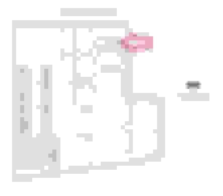
Oops, it turns out the transmission cooler is a separate unit, much like a small radiator, between the main radiator and the AC condenser. I had been thinking the transmission cooler was built into the main radiator, as on many vehicles. More details in this training guide, on page 63:
Bump to an older thread. I had previously discussed the tight clearance with the throttle body when removing the shroud and fan motor. I had a couple of suggestions at the time, including removing the throttle body.
I got to looking at the clearance problem while doing some other work recently. I don�t think you�d have to completely remove the throttle body. I bet if you removed the four mount bolts, you could move it aft just far enough for clearance. There�d be no need to undo the electrical connectors. The coolant lines and PCV tube should have enough flex to allow the small movement needed.
You would want to replace the gasket after having the throttle body loose. It�s Fel-Pro #61351.
As you wrestle the shroud free, you�re going to run into some interference with the throttle body. This is a staged shot during installation, but it gives you an idea what to expect. There is enough flex in the shroud to force the fan motor past the throttle body, but I have a better idea if I ever have to do this again. One option is to remove the throttle body for better clearance. Another thought is to remove the three fasteners that secure the motor to the shroud. Back up a second, and you should first remove the fan blade from the shaft (remember those lefthand threads!). I need a guinea pig to try this, but I think removal would be a lot easier if you removed the fan blade and unfastened the motor from the shroud. No promises, but it�s worth a try. Don�t forget to unplug the connector from the motor if you�re going to try it:
A little update. The radiator had a leak so I replaced it. I figured out a little tip for snaking the shroud past the throttle body. I loosened the three nuts that secure the fan motor to the shroud. (I left the fan blade securely attached to the motor shaft, and did NOT remove it as previously suggested.)
I didn't remove the three nuts, only loosened them so each one still caught by a few threads. This let the motor body move forward relative to the shroud. It was only about 1/4", but this extra clearance was enough to make removal/installation much easier.
Awesome! How much would you charge to refurbish one? These first gen s types are going to need a solution in the near future as decent fans will become more difficult to find.