When you click on links to various merchants on this site and make a purchase, this can result in this site earning a commission. Affiliate programs and affiliations include, but are not limited to, the eBay Partner Network.
My 2006 S-Type 3.0 was throwing out a number of HO2 sensor failures, lean banks, catalytic efficiency flags, etc, which were traced to a failed lower intake manifold gasket. The catalyst was completely destroyed, and one of the downstream O2 monitors had a completely melted tip.
As part of the overhaul, i replaced both catalytic converters, both upstream and downstream O2 sensors, upper/lower intake manifold gaskets, fuel injector seals, IMT seals, brake booster connector on the back of the intake manifold, and spark plugs. I also replaced the fuel filter.
The vehicle now throwing out P0036 and P0056 codes, indicating a problem with the downstream heated O2 monitors. So I followed the pinpoint tests "I" and "M" of factory service manual, designed to troubleshoot downstream HO2 sensors and heater control circuits.
"I2" and "M2" pinpoint tests fail the resistance test as follows: 650 Ohm measured instead of 10 K-Ohm, indicating short circuit to ground. The resistance goes up to 1.2 M-Ohm when the harness is disconnected form the ECM. The resistance between the ECM harness and PIN2 reads 0.4 Ohm, so wiring is intact.
Unfortunately, there are no other tests I can perform. I'm suspecting the ECM has been damaged by a previously melted O2 sensor, which likely created a short and drew too much current. According to the wiring scheme, PIN1 (+) and PIN2 feed the heater coil. Given PIN2 must supply (-) to power up the heater coil from the ECM, I'm guessing it's driven by an n-channel FET inside the ECM.
Are there any issues with attempting to repair the ECM? Am I on the right track here?
They usually are not damaged but of course that's only usually.
In case yours is, there are places that repair them or if you're used to SMD etc then it's potentially DIY. (SMD - if you don't know it then don't plan to DIY this.)
I don't see how you've ruled out a short (quite a high resistance one) from the harness to (somewhere).
A damaged harness has occurred far more often than a damaged PCM (ECM). (Typically the damage has been behind the front bumper or up above the wheel arch (sorry, wheel well) liner.)
If there is a fuse box or the like involved then that's another (low chance) suspect and of course any connectors/relays/etc as 650 ohm could easily be a rather dirty/wet path.
I don't see how you've ruled out a short (quite a high resistance one) from the harness to (somewhere).
As a quick update, I took out the ECM and took the mainboard out of it. I confirmed that 650 Ohm is on the ECM board by measuring the resistance between PIN 88,89 of PI300 main ECM connector (goes to PIN2 of the right/left hand catalytic O2 monitor) and PIN1 of the FH300 secondary ECM connector (goes to ground). In addition, with harness disconnected, I tested continuity of PINs 88,89 of PI300 harness against all other wires in PI300 and FH300 harnesses - all show infinite resistance.
So...given the 650 Ohm path to ground is confirmed on the ECM main board, I'm going to start tracing that issue. I am comfortable with SMD rework.
Does anyone know if the schematic for the ECM exists anywhere?
You can be sure the schematic will not be available (sadly).
Once you can identify the IC (power MOSFET or whatever) concerned you can hopefully find its datasheet online and figure what 650 indicates (and of course check there's no other device in that part of the circuit).
It's odd to have BOTH be bad. Generally P0036 is very rare. So is P0056 so to have BOTH makes me wonder what's occurred.
I think the main CPU chip will be SH705x (x=5 or higher) but I expect it drives some other IC to provide the output current.
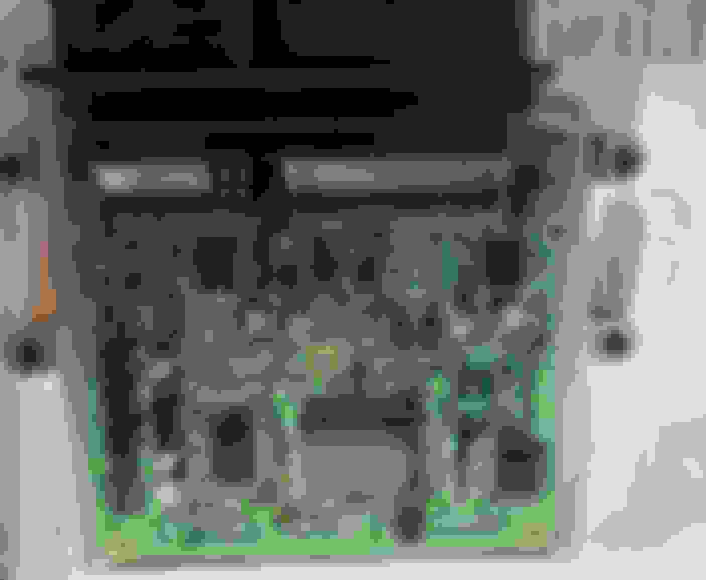
Board is sealed with acrylic polymer - I had to use acetone to remove it in order to make a reliable contact with IC pins. Issue was traced to IC403, which appears to be a 6-channel power FET (heatsink is on the bottom side of the PCB). It supplies (-) to catalytic O2 monitors on 2 out of 6 channels, and both channels are hosed. Others channels read 3.0 M-Ohm. Adjacent IC402 and IC403 are the same PN, and also read 3.0 M-Ohm on all of their channels.
The IC in question is Freescale SC900724 (151821-1510). No datasheet could be found, but its definitely an automotive grade part. Just to be certain, I'm going to desolder the IC to see if the issue goes away (in case there are other circuits feeding the trace).
If confirmed, my options to buy it are: (1) used ECM used for parts, or (2) Aliexpress.com for about $3.00 shipped to USA. Thoughts?
I'm not sure how it exactly does it for this circuit kind but for the PCM to see the fault it has to be sensing what happens to the current that IC is supposed to be delivering. (I'm sure you know this.) I reckon that doesn't account for 650 ohms which sounds horribly like a destroyed gate but removing the IC may let you find out.
aliexpress may take a while. I always worry about the parts but almost all have been fine - but haven't bought MIL or automotive grade.
Used PCM for parts should be OK. (May be cheap or not...)
(In theory a used PCM can be reprogrammed to match your car but this needs real care to get the right data into it rather than its (wrong) data spread around your car or a horrid mix of the two sets of data ending up all around.)
Interesting thing to note is P0036 and P0056 did not exist until after I replaced everything. I realized that I kept the original downstream O2 sensors, one one of which had a melted tip. I measured the resistance across the old heating coils, and it read 12 Ohm on one, 14 Ohm on the other, resulting in a maximum current draw of ~1.0A. Incidentally, the new sensors I replaced them with measured 6 Ohm each, which implies that the new after market downstream O2 sensors draw ~2.0A each, or twice as much.
So I'm wondering - since both channels are fried, could it be that the aftermarket O2 sensors with lower resistance coils inadvertently drew too much current from FET? Is there any data from Jaguar on what downstream O2 heater coil current rating should be?
I'm surprised at the 12/14/6 ohms as the one I bought for a failed one (an upstream, wideband) was only about 2.3 ohms (and matched the good one still on the car).
Found two 651 Ohm resistors on the back of the EMC PCB pulling the lines to ground, so...nothing wrong per the electrical layout, however, completely incompatible with the expectation of a PINPOINT TEST "I2" and "M2" which would result in a 100% failure, unless the EMC is unplugged - which is only requested to do in "I4"/"M4".
Tentative conclusion: Factory Service Manual either forgets to instruct unplugging EMC in "I4"/"M4" pinpoint test, or it is wrong. Thoughts?
Well, the manual might be wrong. That section looks to have been added later on in the production run. I believe P0036/56 were not flagged on the cars before 2006MY - which is most of the cars. I think the PCM changed somewhat (as it had done hugely for the 2002.5MY (2003 USA) cars) to improve emissions control and so on.
I don't know who would know more (well, JLR UK but they aren't likely to help on this stuff).
If so... apart from resoldering the IC you're back to troubleshooting
I was using S-Type 2002.5 MY Factory Workshop Manual, and pinpoint tests "I" and "M" were associated with P0036 / P0056 troubleshooting, covered by the manual:
Not sure hot to troubleshoot now - will place the IC back and will try to put the old O2 sensors in and see what happens. Sucks that I have to guess now...
So...it turns out my speculation was correct. I reached out to Freescale (now NXP), and they said that SC900724 is a custom part, but it is based and linked to another chip MC33882, for which the datasheet is readily available. What do you know, according to the datasheet is is a 6-channel low-side FET, as speculated!!! And to top this off, if the SC900724 has the same 1.0A current limitation as the MC33882, then it would explain why old downstream O2 sensors were 12 Ohms (= 1.0A current draw), and why the new replacement sensors with a resistance of 6 Ohms (~2.0A) would cause issues.
Additionally, the datasheet indicates that the IC has over-current and short protection, so hopefully the SC900724 I removed yesterday is not damaged. I just soldered the SC900724 back on the ECM main board and will give it a test later today. Maybe the problem code will go away once downstream oxygen sensor with the correct coil resistance is placed back. Fingers crossed!
Additionally, the datasheet indicates that the IC has over-current and short protection, so hopefully the SC900724 I removed yesterday is not damaged. I just soldered the SC900724 back on the ECM main board and will give it a test later today. Maybe the problem code will go away once downstream oxygen sensor with the correct coil resistance is placed back. Fingers crossed!
Any updates? Seems like you made a very good find, just wondering how it all panned out with the correct oxygen sensor.
I'm back! I soldered the original SC900724 IC back, and instead of new high-current draw downstream cat monitors, I connected plain turn signal bulbs that draw only ~0.5A to the circuit feeding the coils. I left the key on, and cranked the engine, but the light bulbs did NOT light up, which tells me that (1) either SC900724 has truly failed, (2) soldering / resoldering job did not go well (even though there were no shorts, or (3) there are other issues in the circuit that related to SPI communication or direct pin control of the two channels that supply low-side to the O2 sensor heater coils.
Furthermore, I decided to purchase another set of oxygen sensors, except this time I chose a real brand - Bosch. They arrived today. Needless to say, the resistance on the coils for the second set of new Bosch sensors is, in fact, 16 Ohms - which would create a current draw of only ~0.75A - well within the 1A limit of the FET in question. It's also aligned with 12-14 Ohms I saw in old sensors, and supports the earlier finding that the aftermarket "compatible" downstream replacement sensors that had 6 Ohm resistance (~2A) were, in fact, not correct....
I have some work cutout for me, and will try to provide feedback as repairs are underway.
the resistance on the coils for the second set of new Bosch sensors is, in fact, 16 Ohms - which would create a current draw of only ~0.75A - well within the 1A limit of the FET in question. It's also aligned with 12-14 Ohms I saw in old sensors, and supports the earlier finding that the aftermarket "compatible" downstream replacement sensors that had 6 Ohm resistance (~2A) were, in fact, not correct....
Don't mean to sidetrack you, so ignore me as needed. Just wondering if you had set up a test circuit to measure the amp draw of the heaters in action, not just the static resistance. From my experience, a resistance measurement of a heater element (or even an incandescent bulb) can be WAY off once the current starts flowing.
You bring a valid point. The resistance of the filament does depend on temperature and cold current draw is expected to be greater then when the filament is hot. To that extent, the reported resistances only applied to cold measurements! I'll get more data tomorrow to support some of these observations and speculations.
After putting the SC900724 back, and installing quality O2 sensors from Bosch, the car runs great. I have put 100 miles since the overhaul, and no check engine light so far, which is something that I was staring at for the last 4 years.
With that said, I am now trying to complete all on-board readiness tests to pass the emissions. So far I have followed the generic drive cycle test outline below:
Needless to say, after performing this test, there were still no check engine lights. However, the scanning did reveal stored codes P0174 and P0176. Even though ECL did not illuminate, should I be worried?
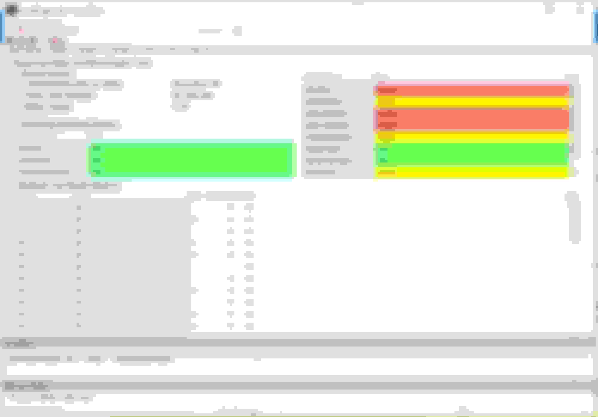
With respect to readiness, AutoEnginuity shows the following still not being completed:
I think I'm getting to the end of the journey here...just need to get over this last hurdle. Any direction is highly appreciated!
I don't offhand recognise JLR 20 90 18 3E so which jag doc is it please?
Usually the monitors complete (aka run OK aka set) after a bit of driving. It needs to include a cold soak overnight and not too little or too much fuel as you're aware from your other thread (re EVAP).
The older P code doc only somewhat applies to your era car - I suspect.
There are newer Jaguar OBD docs. They cover such as 2005MY, 2006MY etc. Your car may well be 2006MY (but car date is not MY and so on, so beware).
The one I suspect you need is on here somewhere and looks still to be at http://www.teacher.starenvirotech.co...6%202006MY.pdf
The thing is, if other than EVAP won't set fairly easily then I'd be worried.
I don't offhand recognise JLR 20 90 18 3E so which jag doc is it please?
The particular document cover page is below, and I'm also attaching the full version here. The cover page indicates that S-Type 2002MY and newer are included, unless I'm not interpreteing "onwards" correctly.

 04-13-2018, 06:56 PM