When you click on links to various merchants on this site and make a purchase, this can result in this site earning a commission. Affiliate programs and affiliations include, but are not limited to, the eBay Partner Network.
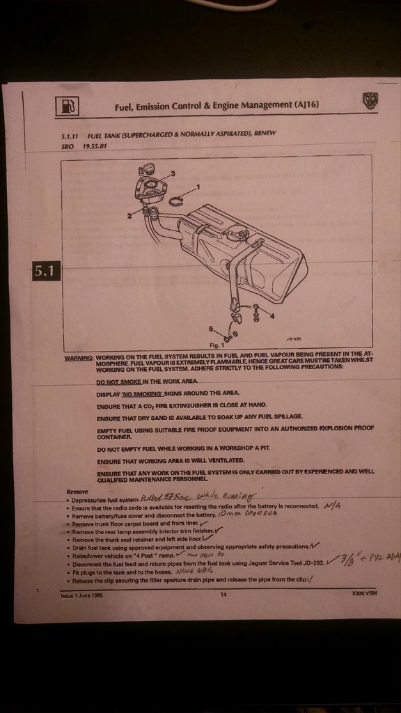
The process of renewing your fuel pump is not the easiest service you can perform on your car, yet it need not be a reason to hack your Jag to pieces. I printed out the procedure from my X300 Service Disc and worked my way methodically through the checklist. Unfortunately, when I got to the re-installation step, �Refit in reverse order of removal procedure� instead of methodically stepping back through the checklist, I went from memory. Don�t do it like I did and maybe you�ll only have to do it once!
I employed the following tools:
10mm �shorty� ratchet/open-end wrench
6mm deepwell socket
7mm deepwell socket
8mm deepwell socket and 6� extension
10 mm deepwell socket
13mm deepwell socket
13 mm shorty ratchet wrench
12� long �� drive extension
Channel-lock pliers
Rubber Mallet
Screwdriver
3/8� A/C-Fuel Connector tool
�Special� locally-constructed fuel-connector-tool leverage device ~ less than 6� section of �� PVC sch 40 pipe
36� section of 5/8� heater hose
O-ring picks
Siphon pump hose:
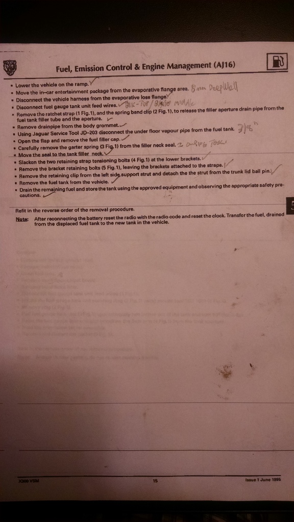
I depressurized the fuel system by starting the vehicle and then pulling fuse #7 from the boot fuse block until the engine quit.
I used the 10mm shorty to disconnect the negative and positive battery terminals. The 10mm socket to remove the battery fixing cleat and then removed the battery. It�s not in the procedure, but I also removed the spare tire/wheel asy and the foam toolkit located under it.
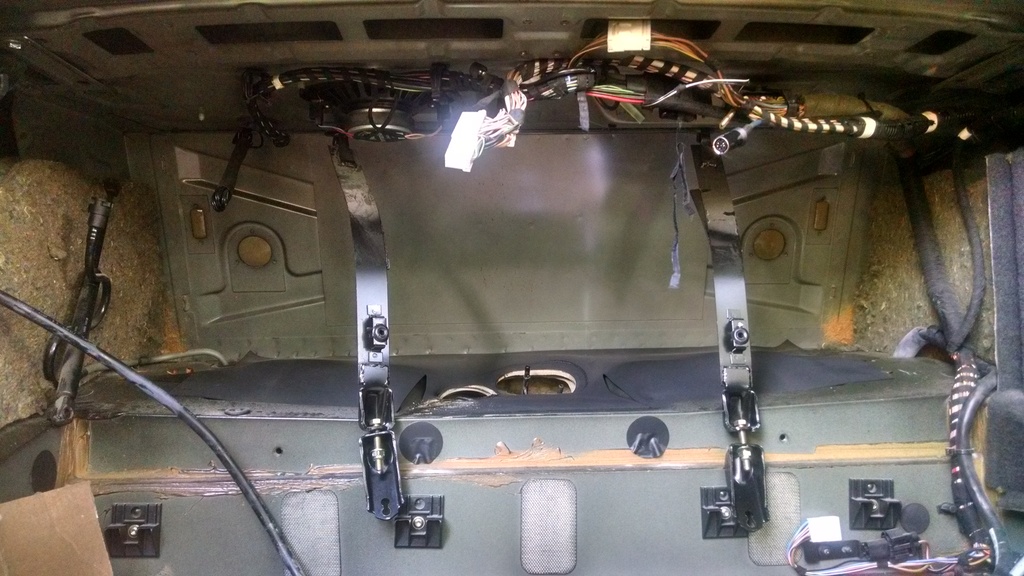
Then I placed a heavy, flattened cardboard box and a foam pad in the boot floor for a more accommodating work surface. Boot front liner and left side trim liner are fairly straightforward, and essentially tool-less removal though a forked body-fastener tool for the pushpins in the front liner may be useful.
Draining the fuel tank is where I used the heater hose and siphon pump. I pushed the heater hose well into the tank and fit the intake side of the siphon pump into the end of it. Even so, after the bulk of the fuel had been siphoned, I needed to twist the hose and work it in and out a bit to get the last bits � or said another way, I got 2-3 gallons out after I initially sucked air. After getting the tank out and removing the pump, I found that it still contained aobut 2-2 � gallons of fuel. No spillage nor leakage upon removal, however.
Not possessing a 4-post lift, I substituted a jack and jackstands. I raised one side as high as my low-profile floor jack would lift it from the left side rear jacking point, then slid my 20-ton air-hydraulic jack under the differential and lifted the entire rear end, placing jackstands at each rear jacking point.
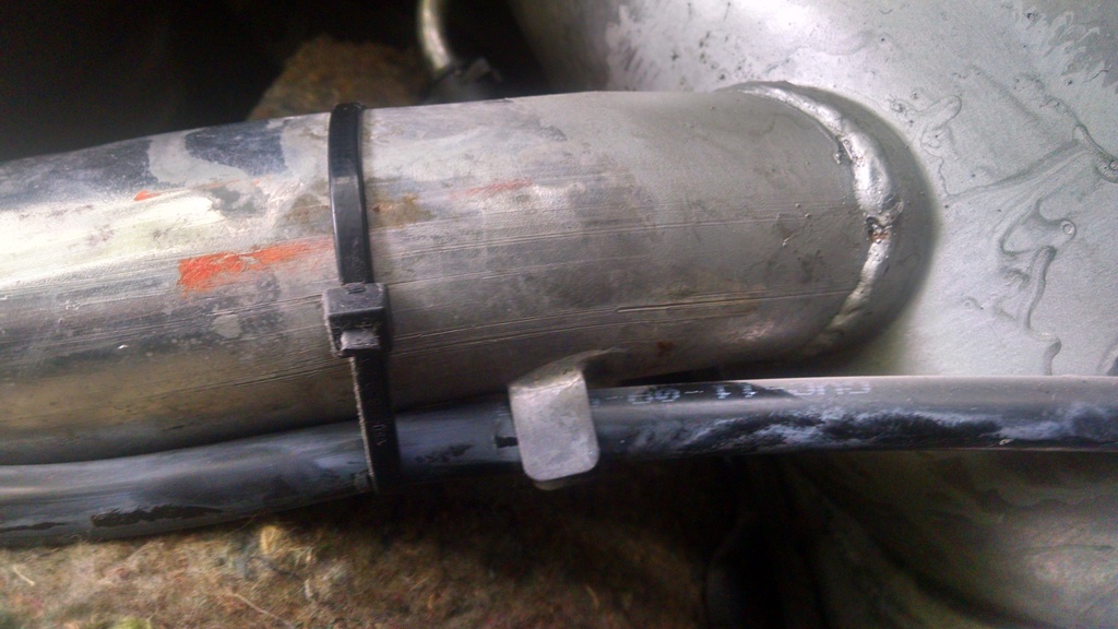
The leverage tool is probably a necessity for disconnecting the feed and return hoses from the tank. It may be possible to push the disconnect tool in and pull the tube free without it, but not for me. Push the 3/8� disconnect tool in until you hear/feel a slight �click� and then give the tube a sharp yank. I didn�t have any plugs handy for the tank nor hoses.
Drain tube is secured by a plastic locking clip, you may need the screwdriver to release it if it�s crudded-up with road grit.
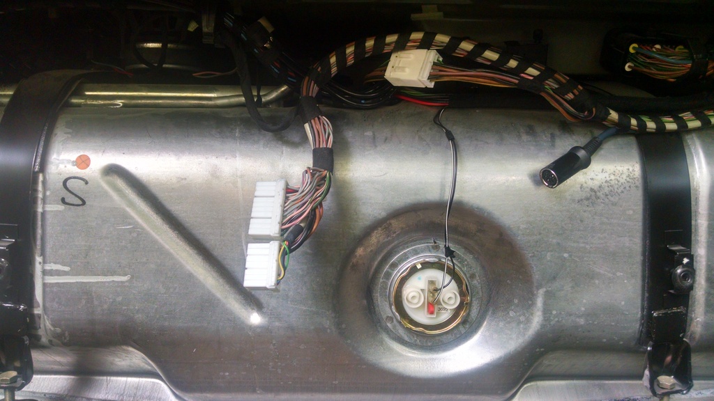
8mm deepwell for removing the CD changer and Amp(if fitted) The electrical connections are �poka-yoke� or �Stupidproof�
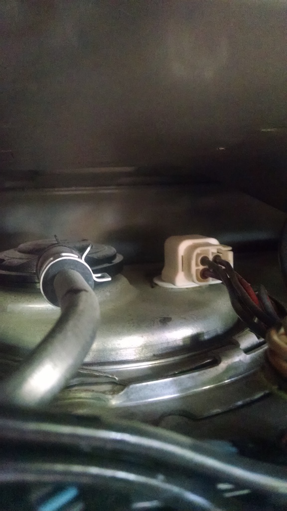
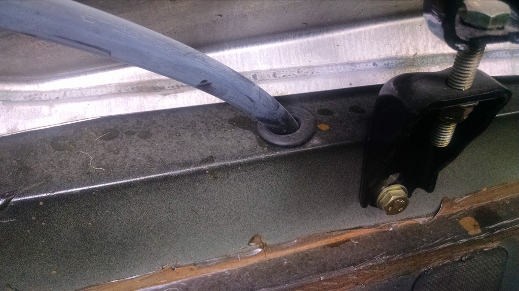
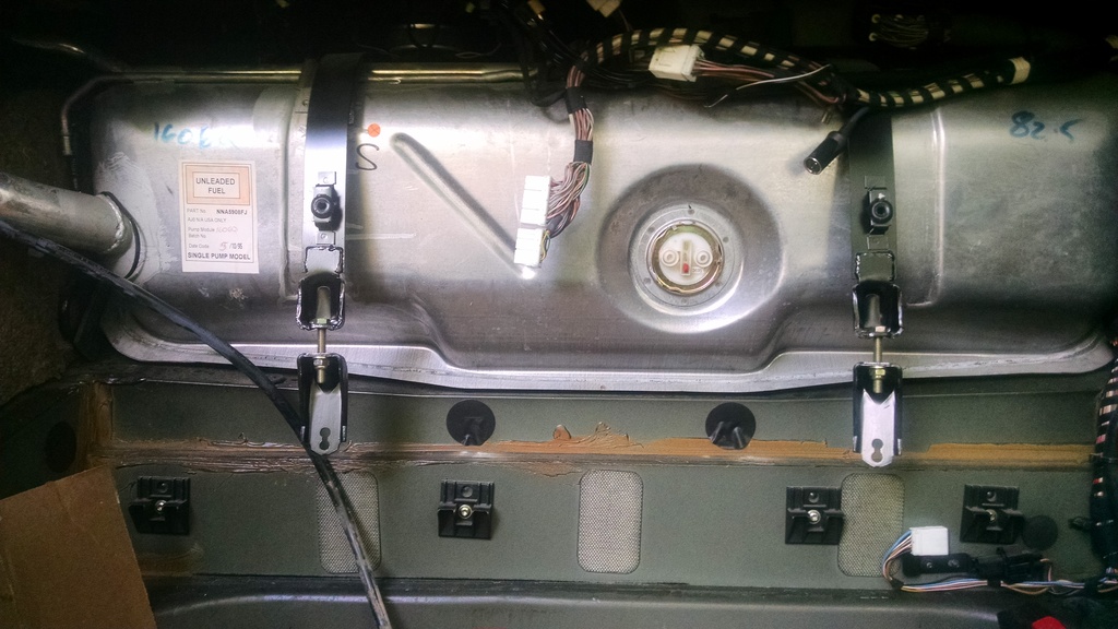
Vehicle harness at the evaporative loss flange has a locking tab on the right side. Squeeze the right side and pull aft.
Fuel gauge sender has two wires, individual spade/fork connectors. Top terminal is the black wire, lower terminal gets the black with white stripe.
The 12" extension is useful for re-installation when you need to thread this drain-tube back through the grommet. It goes through a double-wall hole. Thread the extension up through the grommet from the bottom and have your son slip the drain tube over it and feed it back down through both holes.
The same 3/8� a/c tool you used underneath will release the evaporative loss tube connection, but you won�t need the leverage device.
A couple of O-ring picks are helpful in removing the garter spring from the filler neck seal. I stuffed a shop towel in the filler neck to prevent debris falling in there during removal/refitment
Work the seal up the filler neck to the edge
I used the 13mm ratchet-wrench to loosen the retaining straps and the 13mm socket to remove the lower brackets.
A screwdriver will aid removal of the left side bootlid support strut. (After the tank is removed, is an excellent time to renew your bootlid support struts if they are rubbish)
A helping hand (I used an over-grown 16 yr old lad) is useful for hefting the tank out of the boot. It�s not terribly heavy with 2.5 (US) gal still aboard, but it is a bit bulky when you are sitting on your (brains) in the boot facing forward and you need to get it AND yourself up and out of the boot simultaneously. Pull down/aft on the filler neck and wedge it out left-side first. It is a tight fit at the left boot hinge. I found displacing the plastic hinge cover was the key to success.
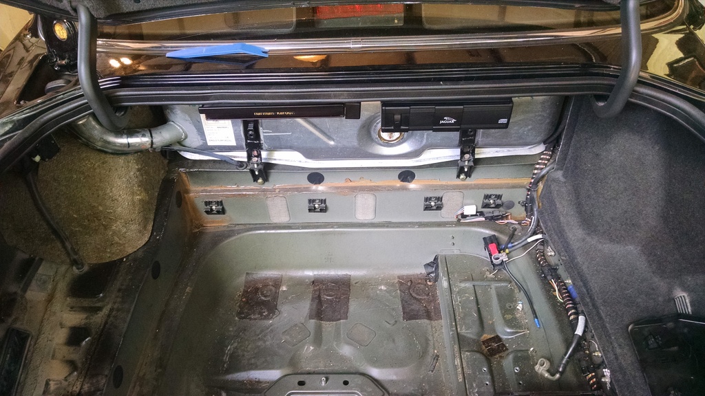
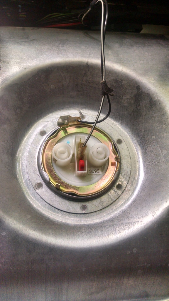
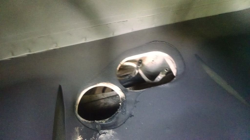
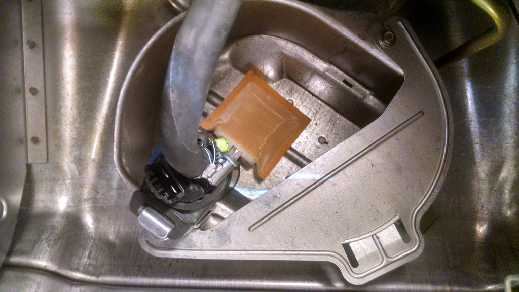
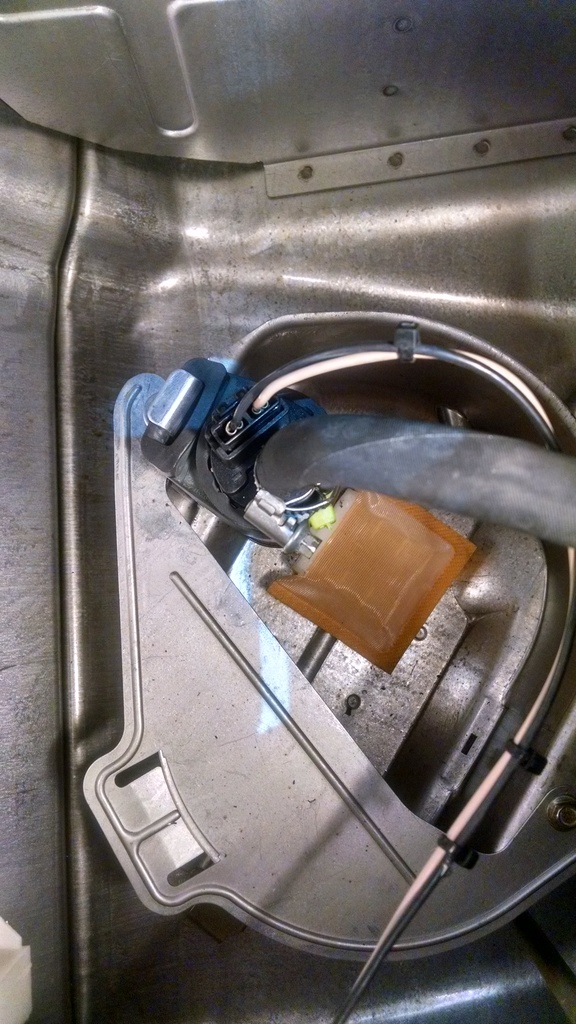
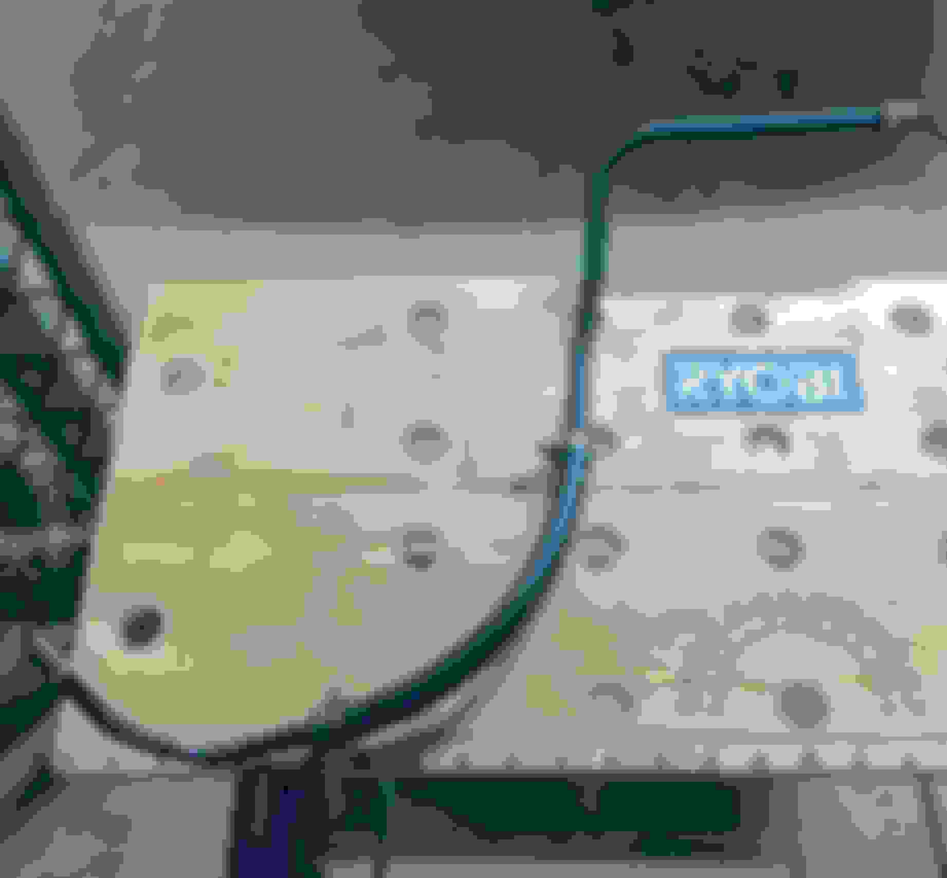
A view with the tank removed from the boot. You can see the feed and return lines peeking up above the hole on the right. The hole on the left is for a drain-plug fitted to the early cars. This 96 just had a flat spot on the tank in that location. It would be useless for draining the tank in-situ as it would just pi$$ the fuel out onto the top of the differential then splash all over the place and hit the floor in about 13 different locations. I reckon your car would smell like fuel for a couple of months and it would be very tough to determine whether or not you had a leak upon re-assembly. All this �assuming� you could successfully actuate the drain. (it�s not a readily accessible area)
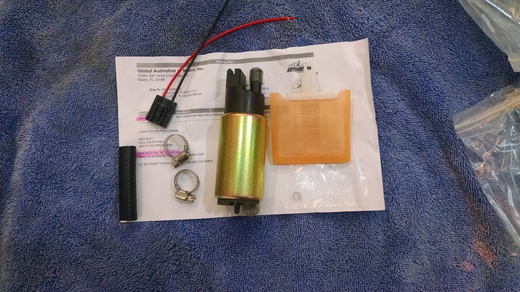
Once on the bench, I released both evaporative loss flange hose clamps with the channel locks and slid them to the steel pipe
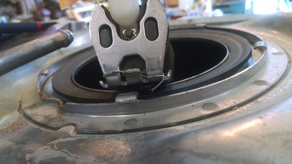
I used the rubber mallet and screwdriver to loosen the evaporative loss flange locking ring by tapping lightly on each tab a few times and moving around the ring to the next one. Probably should�ve used a drift-punch but had the screwdriver handy�..
Disconnect the fuel pump harness from the evaporative loss flange (Don�t forget to �undo� this step on reassembly!!!)
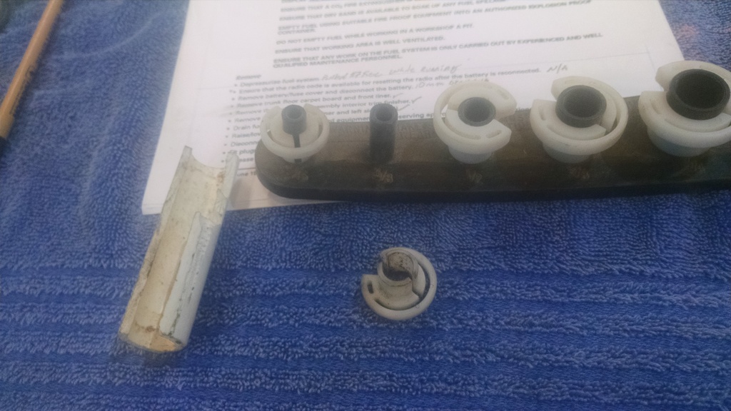
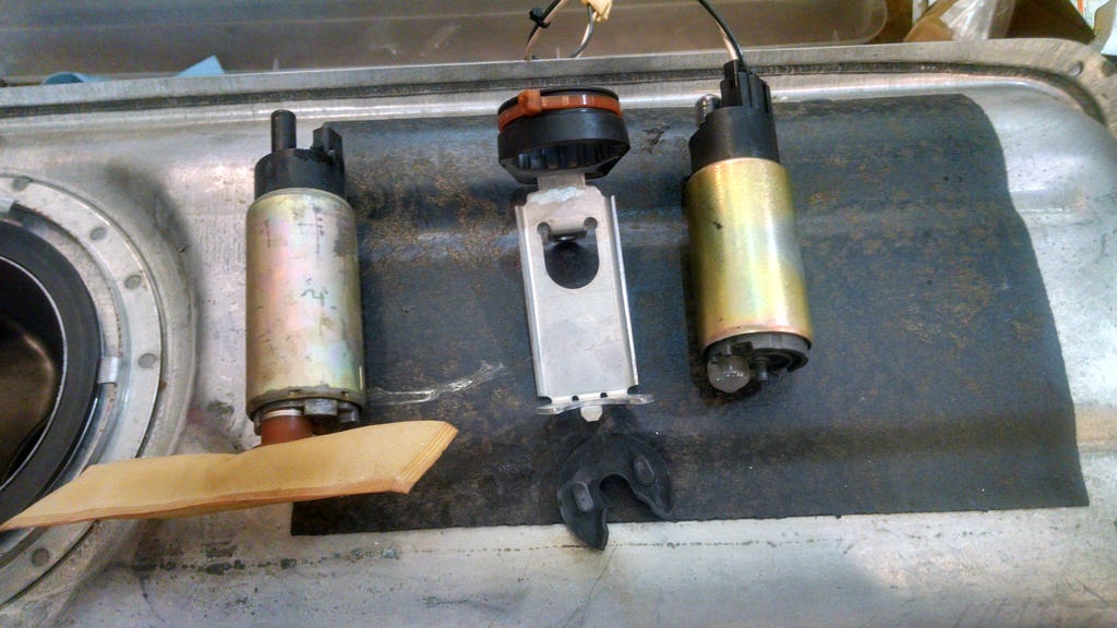
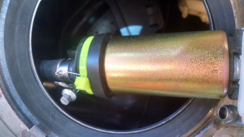
6mm socket will loosen the hose from the pump
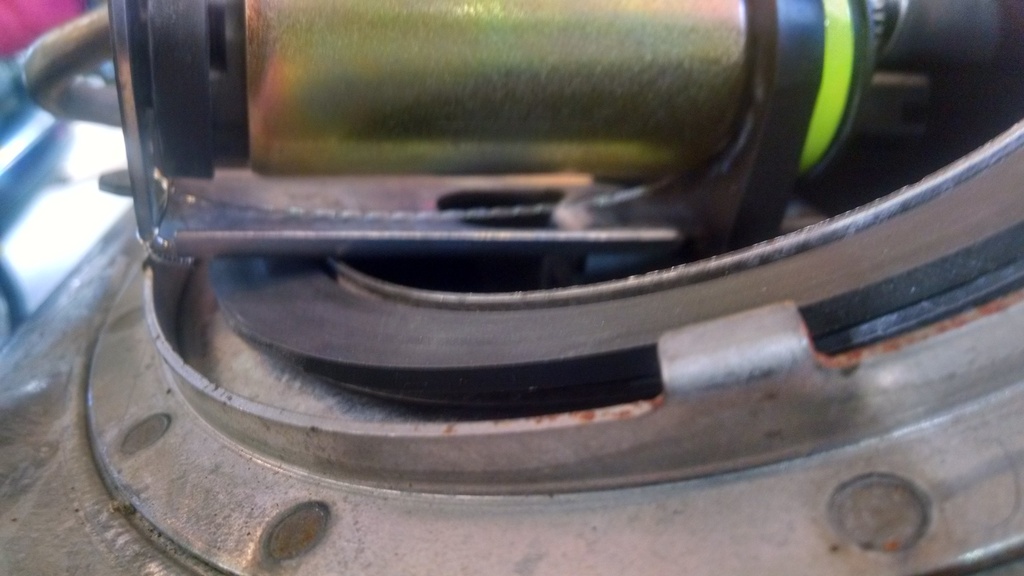
7mm socket will remove the pump fixing bolt from the tank
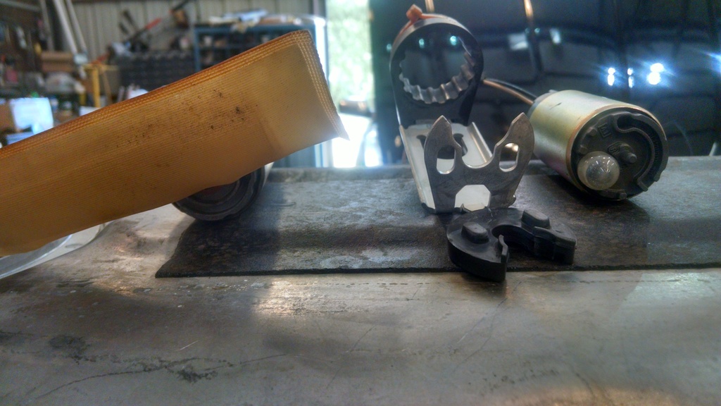
The pump fixing bracket assy includes top and bottom isolators that you�ll need to transfer to the new pump.
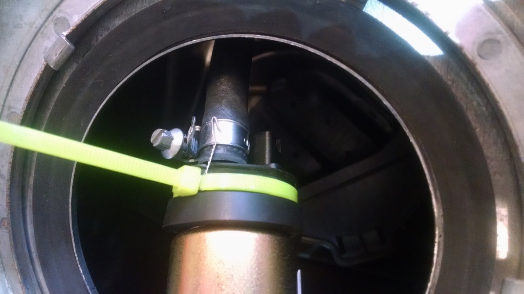
The top isolator is secured with a nylon ratchet strap. After reading reports of pump hose blowoff, I lock-wired the pump hose-clamp to the isolator ratchet strap upon reassembly in an attempt to forestall such an occurrence.
Additionally, since everything seemed kind of loose, I attempted to use lockwire to snug the pump to the bracket, putting a bit of clamping pressure on the lower isolator. All of this activity was accomplished at the top of the tank just outside the aperture, and I believe led to me overlooking the necessity of re-connecting the pump wiring to the evap loss flange.
Although the pump includes a wiring connector, it was unnecessary as the existing harness was an exact match to the pump.
Follow the procedure list in reverse order and you should be fine. I found a smear of liquid soap on the drain tube grommet and filler neck seal eased re-installation a bit. In my case, after I�d plunged the feed and return tubes home with a satisfying �click,� I fit the battery and had my son turn the key on while I rested a finger on the fuel pump relay. A satisfying �click� was heard and felt. Of course, we also had the air-injection pump and cooling fans come on�so there were lots of satisfying �buzzes� but as I was to learn, none of them emanating from the fuel pump. After he cranked it, we had �nothing.� Hmm�maybe it needs a bit more fuel (I�d only returned a gallon after draining the tank completely after removing the pump.) While adding more fuel, it occurred to me that I had no recollection of re-connecting the pump harness to the flange. On a positive note, tank removal goes quite a bit faster the 2nd time on the same day!
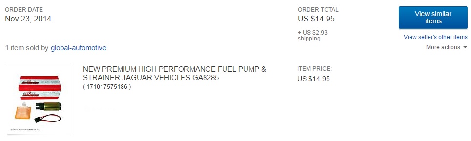
Here�s the pump I used:
The price has come down in the ensuing years, I just ordered two more for $12.50, free shipping!
Now someone simply needs to post an addendum for the steps to also test (verify proper operation) and replace the XJR secondary pump.
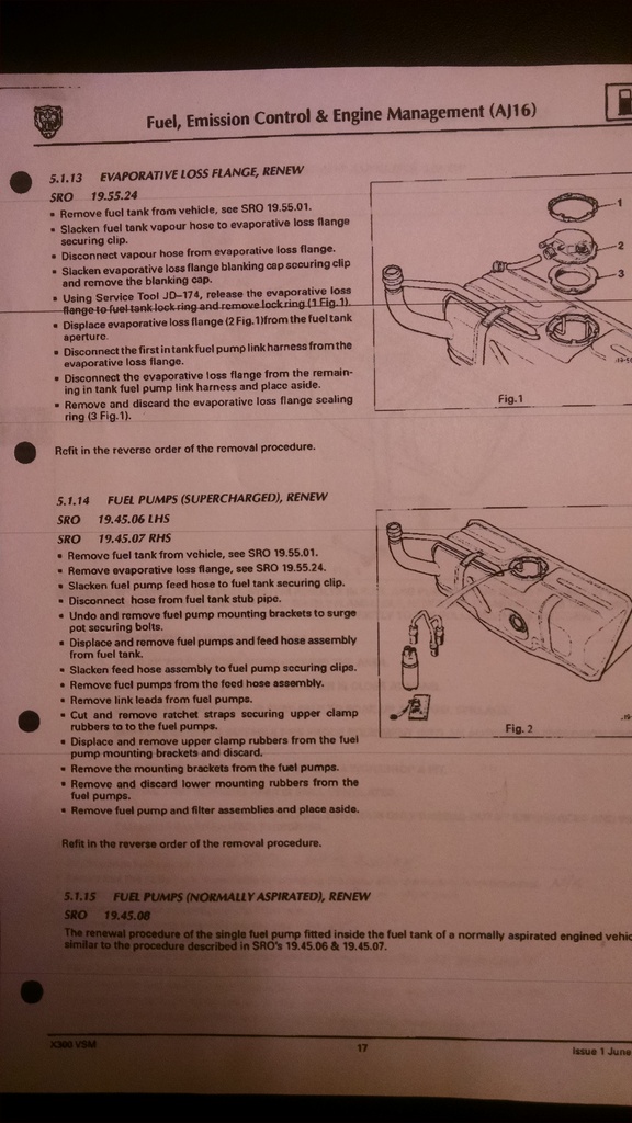
Haha, you have it, Al. See procedure 5.1.14 on page 17? It is the supercharged version. 5.1.15 is for NA cars and is a one-liner at the bottom of the page that says, "If you can't figure it out from how we told you to do the supercharged version..... you probably should take it to someone"
Haha, you have it, Al. See procedure 5.1.14 on page 17? It is the supercharged version. 5.1.15 is for NA cars and is a one-liner at the bottom of the page that says, "If you can't figure it out from how we told you to do the supercharged version..... you probably should take it to someone"
Heh Thanks.
I need to relocate the technical description of how the XJR dual pumps operate. I think they have some unusual operating sequence where the secondary primes the fuel pressure for start, then the primary takes over for regular running, and the secondary kicks in again over 4k RPM... or something like that. ... I forget.
When you disconnect the fuel supply and return lines is there much fuel spilled? I'm wondering how necessary it is to drain down the tank, will fuel siphon out if it isn't drained, or do you drain it just to reduce the weight of the tank to make it easier to handle?
I was north of 3/4 tank so evacuating "some" fuel was mandatory. Once the process was started, no point in not going "whole-hog." I still had about 2.5 gal onboard (but didn't know it - I assumed some was still in there, and prepared myself for a fuel-shower; all I knew at the time is I'd extracted all of the fuel I could) Not a single drop spilled upon pipe disconnect. Both tubes are connected to hoses inside the tank. Supply goes to the pump and I'll need to study my pictures to see if they show where the return hose goes, I didn't take particular note of it. The pump hose arcs up above the half-full level, IMO, so it may be possible you'd start a gravity bleed if you removed the tube connection with that much fuel aboard, but I'm not sure about that. Could be the pump internals are such that no fuel passes unless the pump workings spin.
Opened one of my 2 new pumps today. I see how Global managed to bring the price down: They've deleted the short length of hose and two worm-gear clamps from the kit. Just as well, I didn't use them. In fact, it didn't occur to me until after I'd finished the task entirely (including the second tank-removal) that they are for use at the evaporative loss flange.
I had cause to re-visit this repair and update the post
Here a number of months' on, and the car has developed a long-crank-to-start personality. With the loan of an excellent tool fabricated by Motorcarman, I was able to identify the culprit as a failed check-valve integral to the (very affordable) pump installation documented above. All that diagnosis and discovery is documented in Freebird's thread: https://www.jaguarforums.com/forum/x...firing-178580/
I'll assume you've come here due to a fuel pump problem, and that this news may give you pause regarding the cheap pumps from Global. Do not let your heart be troubled! For nearly the cost (something less) of a second Global pump, you can protect yourself from premature pump check-valve failure by installing an in-line check-valve at the same time you you renew the pump.
A couple of items to note up-front regarding the earlier post that I was either unaware of, or missed the first time around:
First, if you do not empty the tank of as much fuel as you can extract using a pump or siphon and hose through the filler neck, you will get a fuel-shower when you disconnect the (left) fuel feed hose underneath.
Second, when re-fitting the pump, the pump bracket has a tab on the bottom that fits a corresponding slot in the tank baffle at the bottom. Earlier, I guess I got lucky and it slipped right in as I made no mention of it in the earlier posts. This time, not so much luck. From my perspective, unless that tab is seated in the slot, you will never successfully re-fit the fixing screw one-handed!
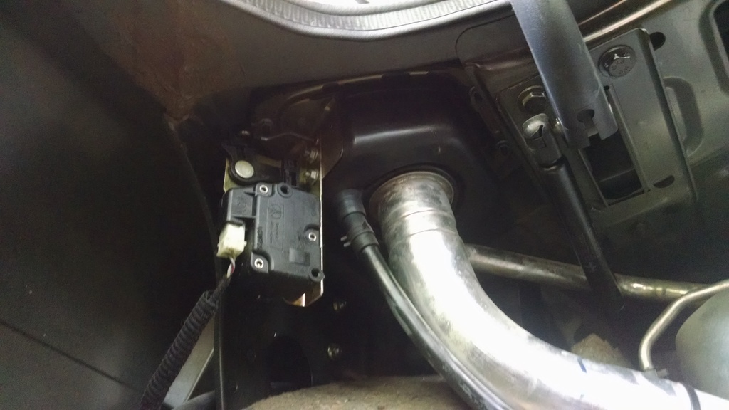
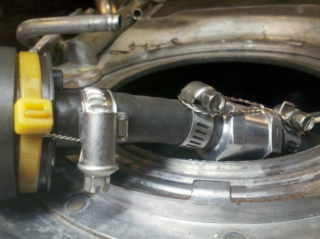
So I popped off the evaporative flange to find this familiar view:
My first thought was to attempt disconnecting the discharge hose and leave the pump in-situ. That didn't pan-out as the pump is very "squishy" in its iso-mounts and it soon became clear a proper fitment would require pump removal. You may recall from the earlier post, I safety-wired the hose-clamp to the iso-mount zip-tie. I was able to leave that undisturbed and just loosen the clamp to pull the feed hose off and fit the short hose for the check-valve in its place. I cut a 2 3/8" section of 5/16" fuel hose to join the pump to the check-valve. Be very attentive and make certain the flow-arrow on your check valve points toward the tank-hose and away from the pump! As you can see, I also wired the clamps together on either side of the check-valve to prevent separation. A&P holders should probably avert their eyes to avoid the onset of nausea at the sight of my wiring.
You need to leave the pump clamp loose enough for the hose to rotate while you refit the pump, then cinch it up tight once the pump is secure.
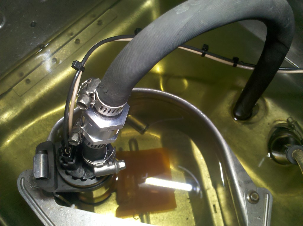
All secure and ready to forget to hook up the wiring again!
Yes! I DID forget to make that wiring connection again....but with age and experience comes wisdom, and I realized that immediately after the last tap with the mallet to seat the ring, rather than after tank installation and start-attempt! Even as I type, the tank is still on the bench....and I'm wondering if I truly remembered to tighten that fuel-pump hose clamp? I may take it loose one more time....
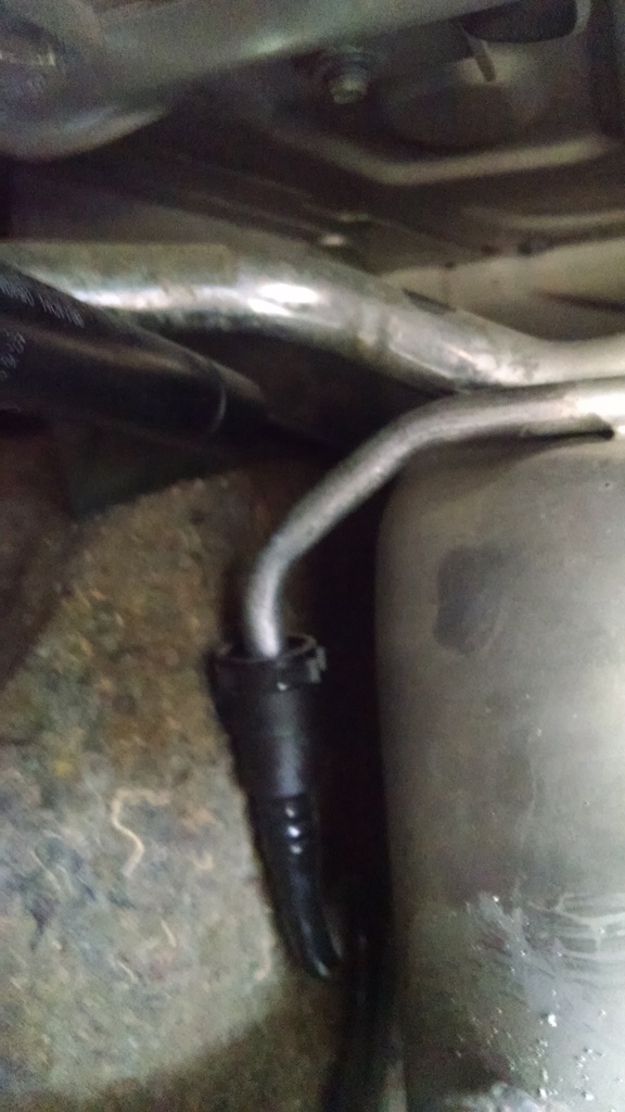
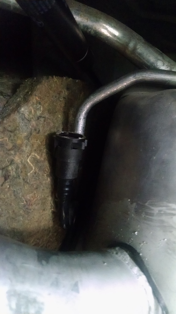
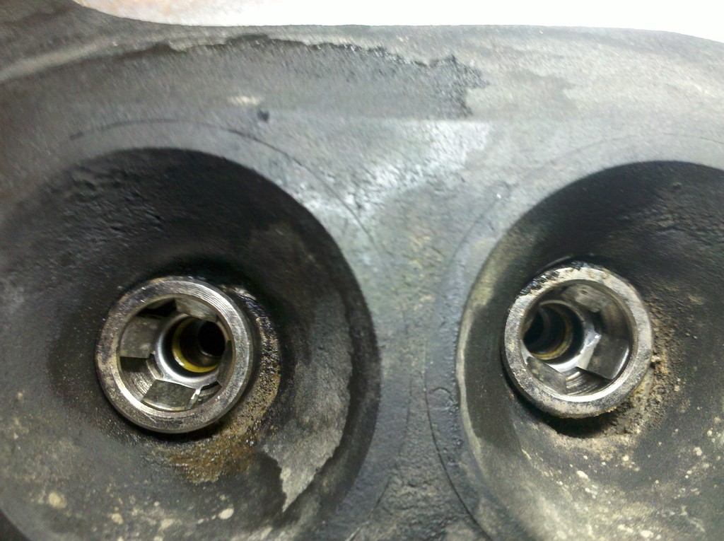
And a random picture of the feed and return ports in the tank in case it's your first time and you are wondering what you're up against...when the tubes won't come free:
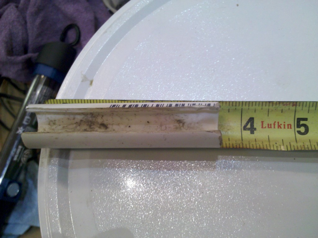
Just realized I never reported further details on the "special leverage tool" as promised in Freebird's thread. I used 1/2" pvc sched 40. 3 1/2" turned out to be the appropriate length for me, after starting at 6". Cut a slot in it axially, wide enough to fit over the fuel line, ie about 3/8" wide.
Could be that slightly longer or slightly shorter would be better if you have smaller or larger hands. For reference, mine are probably best described as "Trumpish," or at least they are certainly smaller than Michelle Obama's.
I'm about to attempt this job in the coming weeks. I see from the photos there is a rubber seal where the evaporative loss flange seats, however I can't seem to find a part number for this item. The Jaguar Classic Parts webpage only mentions a steel flange sealing ring.
I didn't replace it either time I had the tank out. No leaks. Guess it depends on the condition. I DID replace the similar but smaller seal on my '95 when I renewed the fuel-sending unit - but the original also appeared to be in fine shape and wouldn't have hesitated to re-use it had I not had the new one in-hand, already.
In doing some research into the fuel pump replacement, and possibly fitting an auxiliary fuel check valve (in my case two) as shown above as a precaution over the pump's built-in check valve; one thing I found that may be important is to validate the psi specs for the check valve and what its internals are made from.
Based upon my research, the valve shown above is specified for about 40-45psi and I've not seen it rated for in tank use. So that may be a concern long term as it may lose its ability to hold since the psi rating is so close to our operating psi, and I'm not confident it is applicable for submersion in fuel. I'm not saying it is not rated for submersion in fuel, only that I couldn't find any indication that it was.
And as related aside, be aware that one cannot use any fuel injection hose for in-take/submersion. The hose MUST be rated for in-tank/submersion, which is SAE 30R10. If not, the exterior hose jacket will dissolve and turn to a tar mush that will cause hose failure and can contaminate your tank.
So after reading some reviews, etc regarding check valves for high pressure & volume, and in-tank applications, I opted for the following. In my case I chose the Viton version:
Hey , I am about to start changing my pumps on my SC jag- quick question- I am planning on following the check valve lead- any issues on your install also where did you purchase the in tank fuel line- thanks for considering
Nice write up and a good guide for me. I�ve just replaced both fuel pumps in my V12 X305.
A few extra points if I may which may be helpful to other attacking this job.
I syphoned as much fuel as I could from the tank through the fuel filler then I removed the fuel level sender unit and syphoned the rest through that hole, you can see the bottom of the tank so you can see when it�s empty.
I too used a piece of plastic tube to try and release the fuel lines from the tank but only one would release, the other was bent and twisted from someone�s prior hamfisted efforts. The twisted line was the output line which goes to the fuel filter and is quite short with a flexible section. I thought that if I undid it from the filter I may be able to remove the tank with this short line attached. It worked and once I had the tank out I�d the car I managed to get this fuel line to release. Where this line leaves the tank it has a metal tube with 90 deg bend then the flexible bit then another metal tube to the fuel filter. The first tube on my car was almost straight instead of having a bend in it and the flexible part was twisted and kinked and couldn�t possibly have let much fuel through. Picture a twisted garden hose.
Pic of the twisted and kinked fuel hose. Oddly here were no clamps on the OEM fuel line, it appeared to be some sort of heat shrink plastic.
As the OEM fuel line is NLA I replaced the the flexible part with a short piece of high pressure fuel line and a couple of stainless worm drive clamps as shown below. I then sprayed my new fitting with thick underbody paint to protect it from the elements.
Once it was all back together and running the difference in throttle response was noticeable leaving my driveway.
I�m very happy with the results.
Cheers,
Jeff.
Last edited by watto700; Oct 14, 2019 at 11:14 PM.