When you click on links to various merchants on this site and make a purchase, this can result in this site earning a commission. Affiliate programs and affiliations include, but are not limited to, the eBay Partner Network.
Can we all agree that if this works we call this the " @Greg in France method of masking of Jaguar Chrome Turbo wheels"?
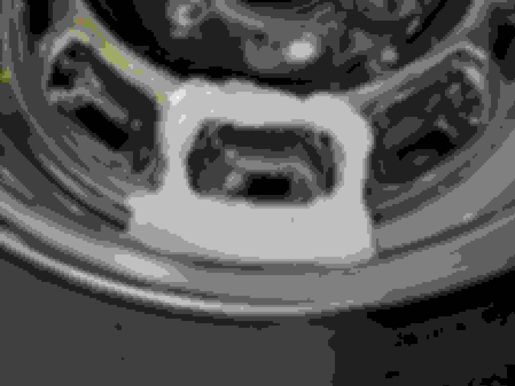
First I made the plug for the areas that should be black out of yellow modeling clay. After I got the shape right I built it up an extra 1/4" and made sure the edges were square.
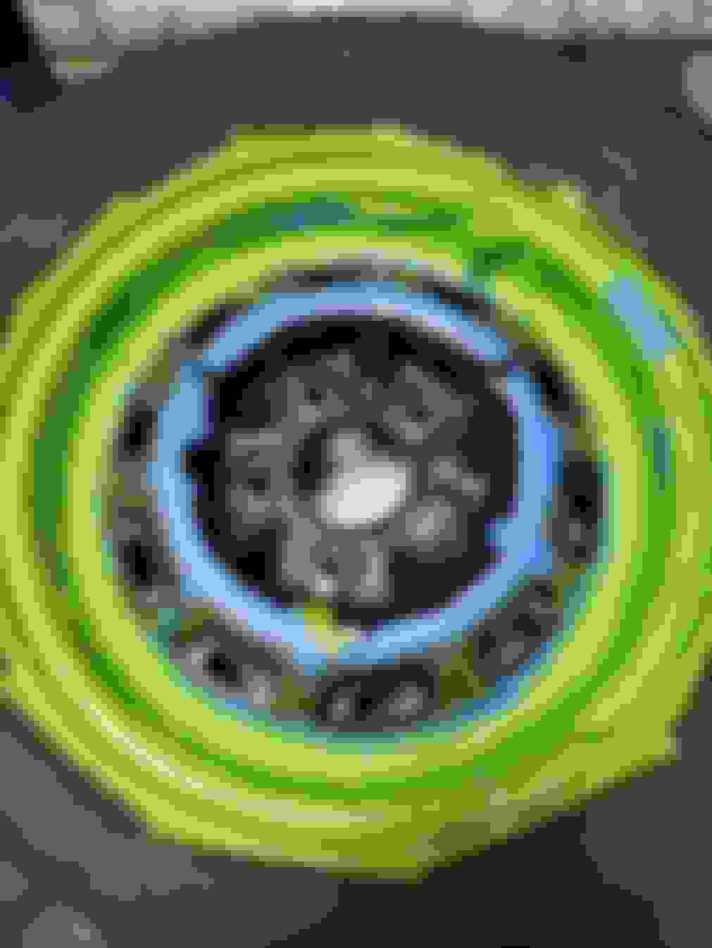
Next I built a dam out of white and yellow clay around the area that is to be masked.
At this angle the damn and plug are close to horizontal. When it arrives I'll use the
to fill up the damn area to the top of the yellow plug. Once it dries that will create a reusable silicone mask I can use to re-paint the black areas.
Next up was the driver's side exhaust system which was going to be the hardest part of the system. It took a couple of tries to get it right but I have a minimum of 3/8" clearance to the steering rack and all the other important bits. It's all just tacked in place right now but once I drop it I can finish welding it up.
My hands aren't steady enough to free hand paint them. It took me 6 tries masking it and trying to cut the template by hand until I got one that looked right. Add to that if they're not perfect that's all I would ever see when I looked at the car going forward.
She's a DRIVER, Thomas, DRIVERS aren't ever perfect! Ya want Perfect, buy a piece of furniture!
I wonder if my my wife could do it. My parents are coming up in a few weeks and they always love a good project - maybe that's something for them to do.
When my parents came to visit, I Always had to have some project for my dad to do or he would crawl the walls.
I bet they would all be Delighted to have something productive to pass the time, as it only takes a couple hours to catch up on family gossip. After that, everyone sits around staring at each other marking time.
(';')
Thorsen
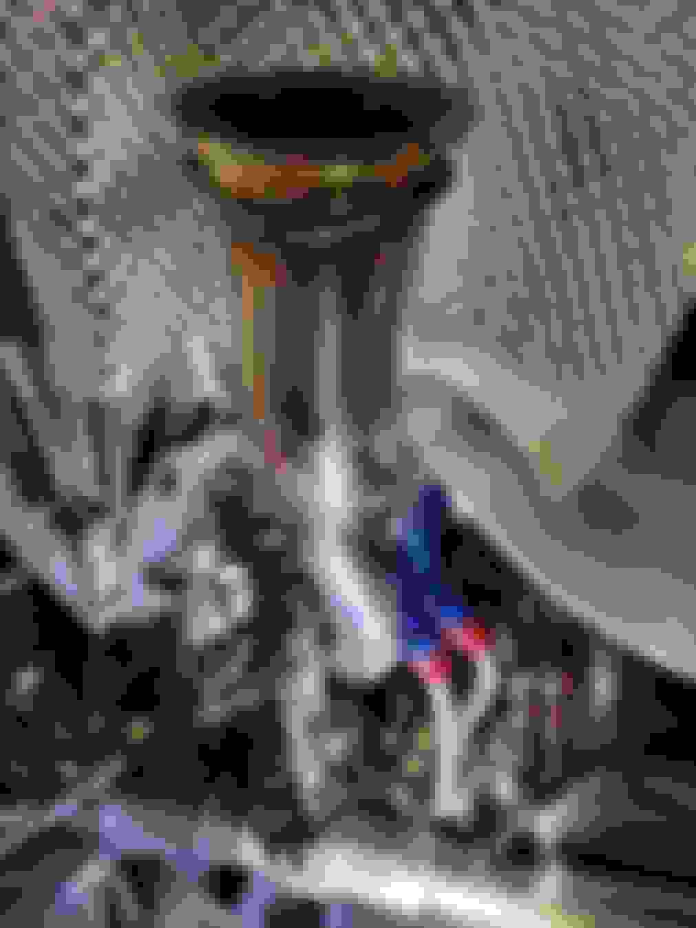
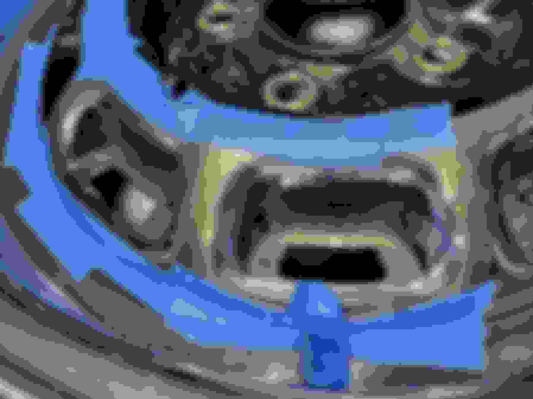
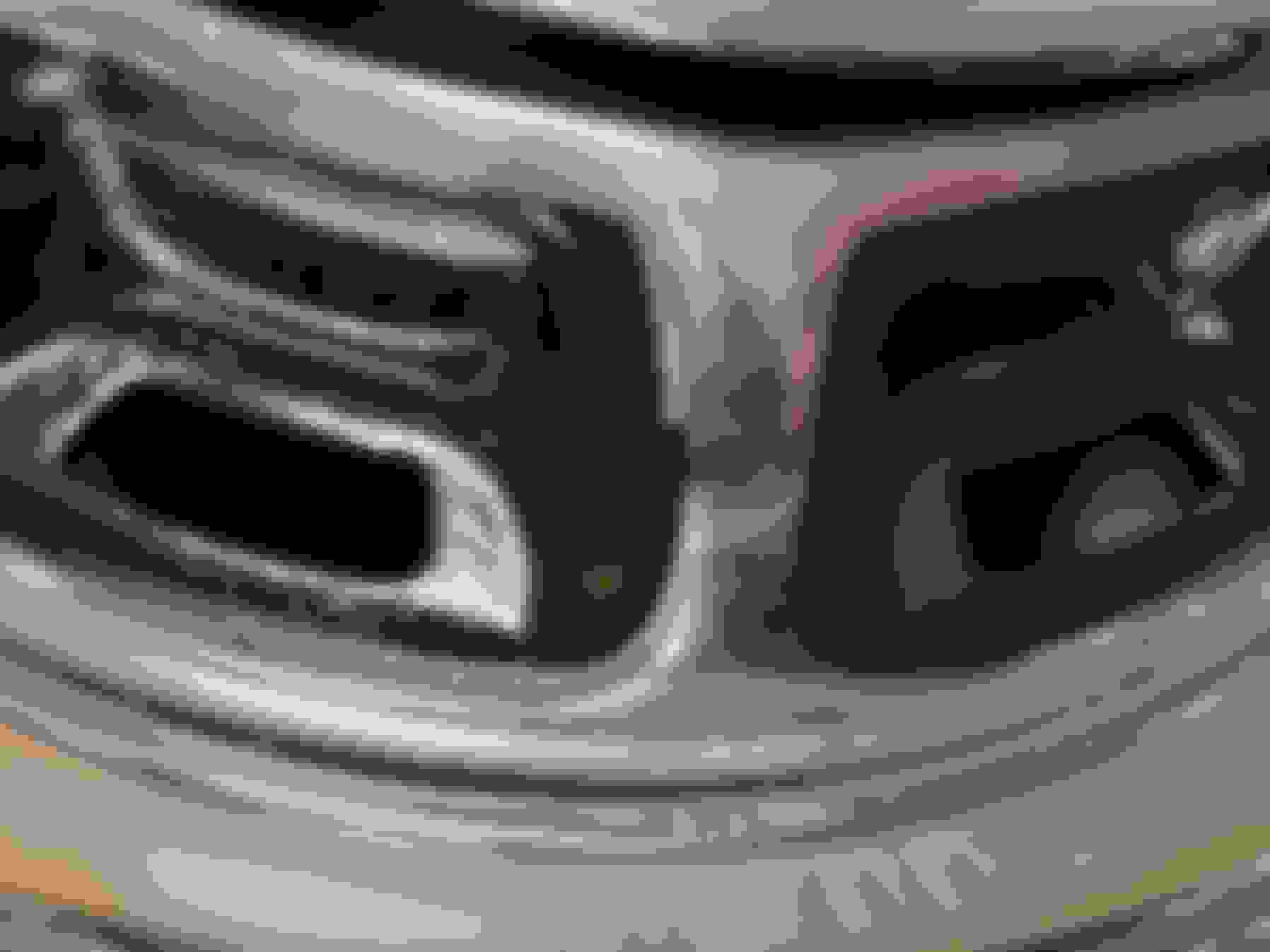
The exhaust route looks pretty good to me, but I slightly worry about the proximity of the lines coming from that piece with Derale on the casting, that look like oil lines, maybe?. Those lines look awfully close to the exhaust when they turn though 90� and go under the exhaust pipe. As in this photo
Could you maybe extend the downwards leg of the blue metal fittings, so as to get maybe an extra inch of clearance, or is it further from the pipe than the photo appears to show? Just a thought.
However, fingers crossed for the Greg/Thomas wheel painting method, your name must be on the system, after all, the development is as if not more important than the initial idea!
Thorsen
The exhaust route looks pretty good to me, but I slightly worry about the proximity of the lines coming from that piece with Derale on the casting, that look like oil lines, maybe?. Those lines look awfully close to the exhaust when they turn though 90� and go under the exhaust pipe. As in this photo
Could you maybe extend the downwards leg of the blue metal fittings, so as to get maybe an extra inch of clearance, or is it further from the pipe than the photo appears to show? Just a thought.
However, fingers crossed for the Greg/Thomas wheel painting method, your name must be on the system, after all, the development is as if not more important than the initial idea!
I agree with Greg, your exhaust is too close to the oil lines. I went back in this thread to find the type of exhaust manifolds you are using, but all I saw were the stock units. My head pipe is about 1/2" away from the rack tower and the tie rod boot. I wrapped an adjacent piece of the head pipe with header wrap to keep some of the heat away from those areas, no problems yet. I think I mentioned before that I'm using rams horn manifolds and route the head pipe to the outside of the rack tower. Makes a pretty straight shot through there. I like Greg's suggestion of using longer nipples coming out of the filter adapter. What size is your head pipe?
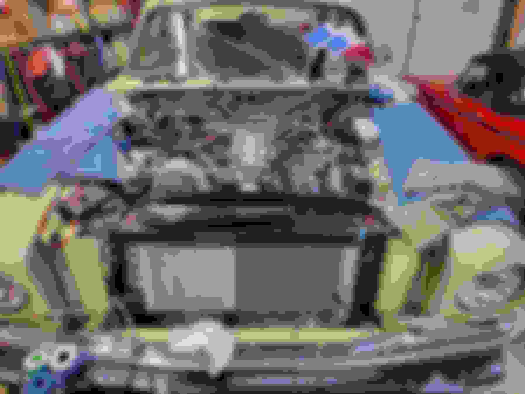
I had started unbolting the downpipe from the manifold when I realized I needed a picture. It was the end of a long day and rather than tighten the bolts back up I just took a picture as-is. When the downpipe is bolted up there is plenty of clearance to the oil lines. With the bolts loosened it sags down and touches.
That being said, I did realize last night that I could run the oil cooler lines against the block and give myself plenty more space. That would afford me some extra room to put a heat shield between the exhaust and oil lines.
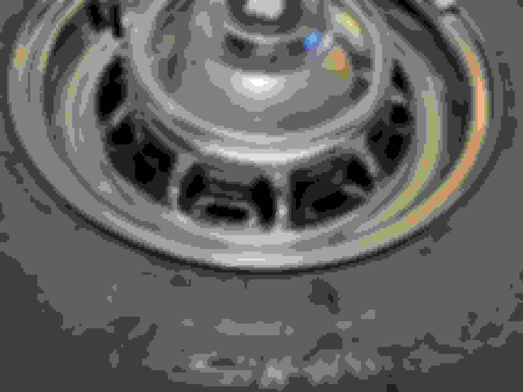
The silicone has dried and after some light trimming I have a paint mask.
I suck at painting things by hand but I had to give it a try. It's not perfect but I bet my wife or Mom can do better than I did.
Back out in the garage I got the driver's side down pipe done and welded the V-band clamp to the end. I also re-routed the oil lines along the block as it was a better path than along the frame rail.
I switched over to the passenger side. The only obstacle here is the starter but working around that was simple.
The passenger side down pipe all welded up and awaiting grinding before the final install. Everything is 304 stainless steel from the flanges to the o2 sensor bungs to the clamps so it takes a little more effort on the cleanup.
Today my wife took a crack at hand painting the wheels with the silicone mold and declared "this thing is worthless". The she tried free-hand painting and decided that wasn't going to work either.
So back to the next layer of the plan - I wondered if cutting the masks I had printed into 4 pieces would make it easier to put them on. The answer is generally yes (more on that later) so we turned on the basketball games and started masking wheels.
I used making tape to bridge any gaps in the wheel masks and to make sure none of the chrome got painted.
More masking tape on the outer wheel of the rim keeps the overspray off the chrome.
I skipped masking the tires as I was not painting the edges of the rim and I felt confident I could keep the spray off the tires.
After 3 coats of semi-gloss black I am happy with how this turned out.
Back to the point about the wheel masks being easier to put on when they are in four pieces, there are a couple of areas where the masks didn't perfectly line up. But those are few and very minor.
I also removed the differential pinion seal. It was dry when I disassembled the rear cage but I noticed some wetness around it while working on the exhaust. I carefully punched dimples in the pinion shaft and the pinion nut and counted 9.5 turns until the nut was off. I'll drive in a new seal and that will keep that from leaking.
Under the car again tonight, I replaced the differential pinion seal and reinstalled the driveshaft yoke and pinion nut back to 9.5 turns.
I also took the opportunity to replace the output seal on the rear of the transmission since I had the driveshaft out of the way.
After that I reinstalled the driveshaft with the AN bolts.
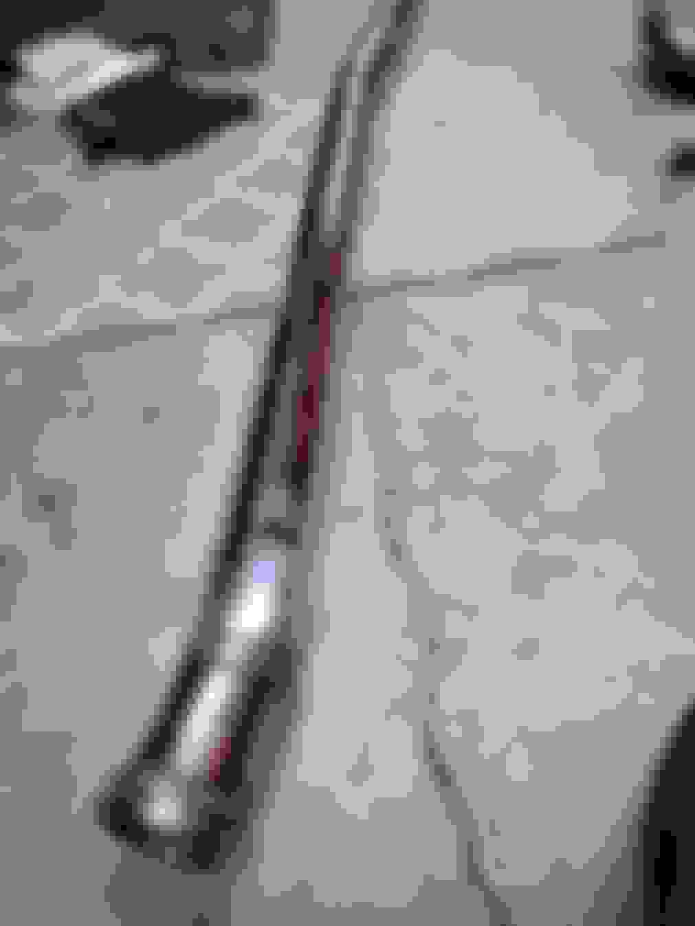
I then turned my attention to the over-axle exhaust pipes. My car is missing the exhaust hanger brackets C41559 and C41560. I found a set on ebay that look like they have spent a couple decades at the bottom of the Atlantic ocean. I decided not to spend $150 on those and just make my own.
Sorry I haven't checked in to your thread in awhile, but I've really enjoyed catching up on your progress!
I love Greg's idea and your execution of the silicone paint mask for the wheel recesses!
Another weapon that might be useful for future readers of this thread is Frisket, or masking fluid, which artists use to mask off areas of a painting that they don't want to receive paint. It's available in liquid form to be applied with an artist's brush, or in pen form like a Magic Marker. Once applied and allowed to dry, you paint the desired areas, then simply rub away the Frisket, revealing the original unpainted surface.
Here's a list of some of the available products. Note that some are only suitable for watercolor paints, while others are suitable for oils and acrylics:
Tonight I finished mocking up and tack-welding the left side intermediate pipe. At the front of the car this connects to the down pipe off the manifold and at the rear of the car it slides into the stock-style muffler under the rear seat.
After it was all tack-welded I pulled it from under the car so I could finish the welding on my bench. The only automotive job I can't stand is laying on my back on a cold garage floor and welding upside down. My next garage is going to have a lift so I can position myself away from the weld splatter.
A busy day in the garage. I started out by making the intermediate pipe for the right side of the exhaust. Here is the v-band clamp that attaches to the down pipe.
I'm using a Bell stainless steel system for the back third of the exhaust system but the right side heat shield for the muffler under the rear seat was missing. I made a new one by cutting a piece of dimpled aluminum heat shield to the correct size, putting a piece of heat shield with fiberglass insulation on top of that, and bolting it in place.
The right side intermediate pipe all finished and ready to be bolted in.
With the exhaust in place, I was able to run the engine until it reached operating temperature. This was the most the car has run since last summer. I was able to get the transmission fluid to the right level, bleed the power steering system, and bleed the air out of the cooling system. I was able to test the heater (it's hot), the vacuum operated fresh/recirc air switch (it works), and the vacuum operated defroster flaps (both work). The alternator is not charging but I think that is related to the dash light circuit. Since the low oil pressure light is not coming on I bet I missed a wire somewhere.
I had a little time this morning to trouble shoot why the horns don't work and I think the heavily corroded power terminal leaving the relay probably had something to do with it.
I also figured out the issue with the alternator - I had a blown indicator lamp which wasn't letting voltage pass through to the alternator to tell it to charge. I just swapped bulbs to get it working, but I need to pick up some spares. Does anyone know the part number for this kind of bulb?
I also got the factory low oil pressure warning light wired up to the switch so I'm feeling pretty good about the car warning me about problems.
I have switched to LED bulbs in my dash and ordered them all from these folks, very good service and postage at the time was cheaper than orders in U.S.
In the "bulb reference guide" look at bulb type 43 and 44 toward the end of the PDF file. 43 is a T5 and 44 is a T10. The part numbers are Lucas, but a parts store might be able to cross, I think they are a common bulb.
Greg is correct. If you use an LED in the alternator warning light circuit you also need to wire in a resistor shunt. A regular light bulb provides enough current to the startup field in the alternator to tell it to get to work.
Greg is correct. If you use an LED in the alternator warning light circuit you also need to wire in a resistor shunt. A regular light bulb provides enough current to the startup field in the alternator to tell it to get to work.
You're right and I did leave the bulbs in the warning light panel as incandescent. The link I sent specializes in LED bulbs, but their bulb reference guide is far-ranging. 43 and 44 are incandescent type.