
S1 Inlet Manifold Vacuum Connections


Thread Starter
|
Senior Member
Joined: Jul 2012
Posts: 287
Likes: 50
From: Canberra, Australia
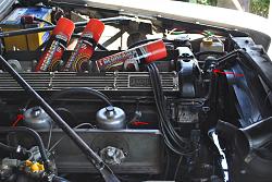
Hi All, I've just put in a replacement engine after a bit of a break between taking the old engine out and can't figure out all the Vacuum connections on the underside of the Inlet Manifold.
I'd appreciate if someone could help me out. It's a RHD car if that makes any difference?
I'd appreciate if someone could help me out. It's a RHD car if that makes any difference?

Joined: Jan 2014
Posts: 28,386
Likes: 6,340
From: Delaneys Creek,Qld. Australia
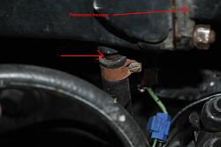
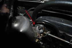
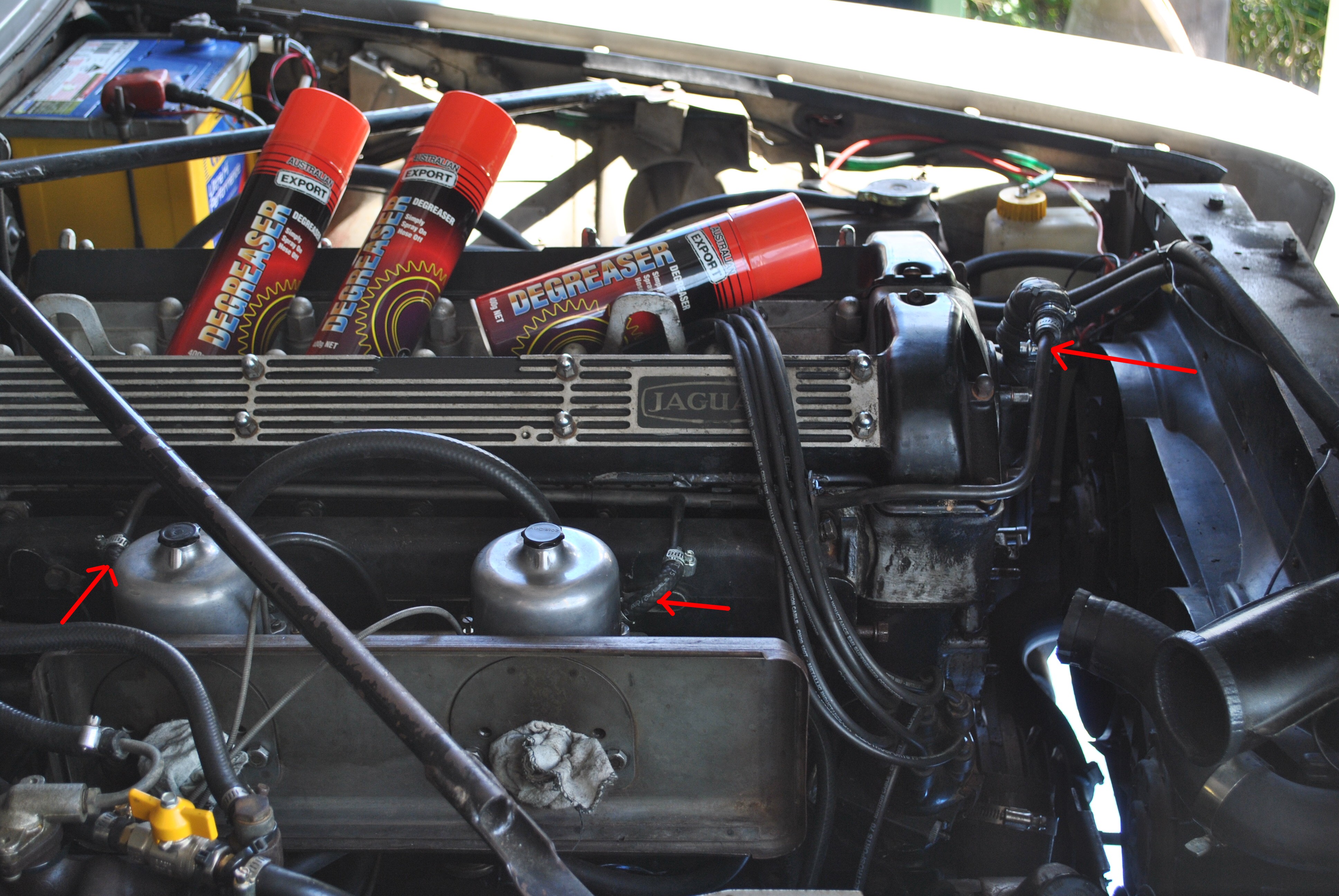
At the front underside of the intake manifold just behind the thermostat housing is a hose(about 1/2") that goes to the brake booster.
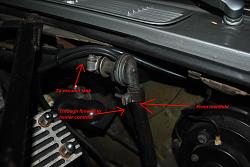
On the underside of the manifold between the two carby's is another hose the same size, it goes around behind the engine to the upper left of the firewall to a check valve the continues from there to the vacuum tank tucked in behind the brake booster.
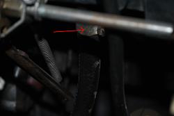
At the rear underside of the manifold there is a small metal 90 degree pipe pointing to the rear with a hose to the transmission vacuum modulator.
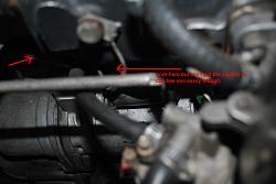
Another larger one connecting both carby's
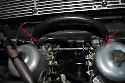
A small hose off the rear carby goes to the distributor.
Both carby's connect to a pipe that is on top of the manifold and goes to the engine oil breather.
Hope this helps

On the underside of the manifold between the two carby's is another hose the same size, it goes around behind the engine to the upper left of the firewall to a check valve the continues from there to the vacuum tank tucked in behind the brake booster.


At the rear underside of the manifold there is a small metal 90 degree pipe pointing to the rear with a hose to the transmission vacuum modulator.

Another larger one connecting both carby's

A small hose off the rear carby goes to the distributor.

Both carby's connect to a pipe that is on top of the manifold and goes to the engine oil breather.


Hope this helps
Thread Starter
|
Senior Member
Joined: Jul 2012
Posts: 287
Likes: 50
From: Canberra, Australia
Clarkey, your are a legend! Many thanks Sir.
I'm actually fitting an S3 Engine and BW66 Auto Trans. I've just retro fitted the Carbs and Manifold. The obvious difference is between the Auto Trans and the method of Kick Down/Down Shift. The S1 uses the vacuum you speak of above (and the one that had me scratching my head) and a micro switch on the throttle linkage, where as the S3 uses a cable operated system.
I think I should be able to work some kind of bracket and have the correct range of travel.
I'll let you know how I get on.
Thread Starter
|
Senior Member
Joined: Jul 2012
Posts: 287
Likes: 50
From: Canberra, Australia
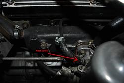
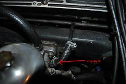
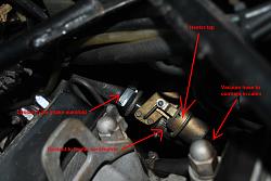
Ok, I've blanked off the rear most underside vacuum connection and have the started now. There is another vacuum pipe (well, I think it's vacuum) that needs connecting. Its the on the valve (some kind of diaphragm valve) that's connected to the coolant pipe coming of the back of the manifold. It has a smaller vacuum size take off?
Edit: Just had a quick look in my Haynes Manual and found out that the new vacuum pipe issue is for the Heater Water Valve Servo Unit. I'll check it out tomorrow.
Edit: Just had a quick look in my Haynes Manual and found out that the new vacuum pipe issue is for the Heater Water Valve Servo Unit. I'll check it out tomorrow.
Last edited by Woznaldo; Aug 16, 2015 at 04:20 AM.
Joined: Jan 2014
Posts: 28,386
Likes: 6,340
From: Delaneys Creek,Qld. Australia
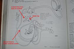
That is the heater tap to let hot coolant into the heater core/matrix. Yours may look different to mine as one or both of us may an after market item fitted.
EDIT, I see your edit now. You found it While I was getting pics.


EDIT, I see your edit now. You found it While I was getting pics.
Trending Topics
Joined: Jan 2014
Posts: 28,386
Likes: 6,340
From: Delaneys Creek,Qld. Australia
All 4 of my service manuals and my original dealer parts book show the same as you have, mine looks like one from HQ-HX Holden.
The pic is from the parts book. It was NOS I found in a second hand bookshop still in plastic with 1973 publishing date inside.
If you are chasing original parts numbers for anything send me a PM and I will look them up.
The pic is from the parts book. It was NOS I found in a second hand bookshop still in plastic with 1973 publishing date inside.
If you are chasing original parts numbers for anything send me a PM and I will look them up.


Senior Member

Joined: Jan 2012
Posts: 552
Likes: 187
From: Ontario Canada
Clarkey, your are a legend! Many thanks Sir.
I'm actually fitting an S3 Engine and BW66 Auto Trans. I've just retro fitted the Carbs and Manifold. The obvious difference is between the Auto Trans and the method of Kick Down/Down Shift. The S1 uses the vacuum you speak of above (and the one that had me scratching my head) and a micro switch on the throttle linkage, where as the S3 uses a cable operated system.
I think I should be able to work some kind of bracket and have the correct range of travel.
I'll let you know how I get on.
I'm actually fitting an S3 Engine and BW66 Auto Trans. I've just retro fitted the Carbs and Manifold. The obvious difference is between the Auto Trans and the method of Kick Down/Down Shift. The S1 uses the vacuum you speak of above (and the one that had me scratching my head) and a micro switch on the throttle linkage, where as the S3 uses a cable operated system.
I think I should be able to work some kind of bracket and have the correct range of travel.
I'll let you know how I get on.
Thread Starter
|
Senior Member
Joined: Jul 2012
Posts: 287
Likes: 50
From: Canberra, Australia
Rob, I had the engine running in the car for couple of years before taking it off the road to fix some non engine related issues.
I recently fire her up and the engine still seems to be running well. I don�t remember too many issues with the throttle linkage. everything went together pretty well?
I recently fire her up and the engine still seems to be running well. I don�t remember too many issues with the throttle linkage. everything went together pretty well?

Thread
Thread Starter
Forum
Replies
Last Post
clubairth1
S-Type / S type R Supercharged V8 ( X200 )
30
Sep 3, 2025 04:38 PM
jcwells
XJ XJ6 / XJ8 / XJR ( X350 & X358 )
3
Sep 24, 2015 09:20 PM
OkieTim
S-Type / S type R Supercharged V8 ( X200 )
3
Sep 8, 2015 04:48 PM
Currently Active Users Viewing This Thread: 1 (0 members and 1 guests)