When you click on links to various merchants on this site and make a purchase, this can result in this site earning a commission. Affiliate programs and affiliations include, but are not limited to, the eBay Partner Network.
Got it back this far, getting a spark on each cylinder, but very hard to see the timing mark on the (?) flywheel can see the marker locked to the engine block with which you try to level the moving marker very clearly but struggled to see the moving marker at all.
Lot of black fuel residue from carbs, all been cleaned and reset recently. New petrol in tank last week too.
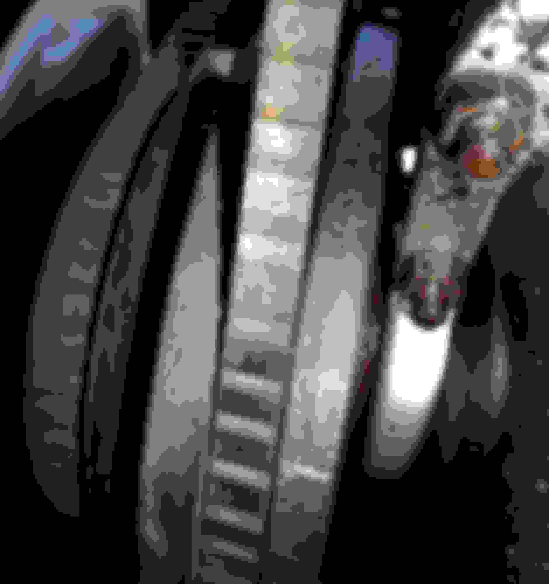
It's not decoding an alien text, but is this correct? the allusive timing mark to be lined up with the static marked on the engine body appears to be marked as 3 before TDC by whoever. does that sound right for a Series 2 XJ6 engine? the camera flash illuminates it, to the eye it is almost invisible.
Maybe the rubber of the front pulley has died, age related, and the outer ring, what the timing marks are stamped into has spun a tad. More common than most realise and admit.
I would be removing #1 spark plug, the rear cylinder, and rotate the engine BY HAND, with your thimb in the plug hels. Whn the compression of teh sompression stroke "pushed" your thumb stop rotating. CAREFULLY lower a soft wire, I sue an opened coathanger wire, done the plug hgole. Continue rotating MORE CAREFULLY, whilst watching the wire rise up. When that "rise" stops, stop rotating. You are now as close as damn it to TDC #1 on the compression stroke.
This is the position you need the engine to be set at as a "base timed" position.
Now the distributor rotor "should be" pointing at the #1 spot on the cap.
NOTE:
This at TDC, and you want about 10deg BTDC (Before Top Dead Centre) for optimum running.
This can be adjusting when its running, as it WILL run at TDC.
I rarely use the timing marks on these older engines, due to things that may have moved/slipped/whatever.
If the slot in the distributor lock plate is hard to the clockwise position, loosen the clamp bolt a small amount, thus allowing the distributor to "slip" inside the bracket to get it where you want it.
If the rotor is not pointing at #1 lead post in the cap, you can simply start the sequence at the post the rotor is pointing at, and continue with the rest in the anti-clockwise direction.
Last edited by Grant Francis; Aug 31, 2017 at 03:41 AM.
All that I can add is that the old way of making the marks on the crank pulley easier to see when stopped or for the strobe was to mark the TDC mark in white chalk,
I found that "white out" used for correcting tyo's on paper was even better.
It's been a while since I had a car that needed that type of attention.
My old strobe is in my box. Still useful to detect the presence of HT in spark pug and coil leads.
If as Grant says, the outter part of the dampener has slipped, the marks nean little if anything.
Right, so what is the size of the wrench tool needed to manually turn that big central bolt head ?
yes, white marker very helpful, the fixed point on the engine body has clear white mark as such.
I have a cone and bolt on the bench somewhere, and will measure it when I get home from work, I think????? its a 6cyl one, might be a V12, dunno. Same I think??
Straight 6 this one. Took a paper impression of the bolt and the sides each look about 19mm roughly so diagonal is 38mm but this is rough as. Grease impression on paper, belongs in art gallery
BTW that's not a 3BTDC it's an 8BTDC which is marked. It should line up with a pointer on the block IIRC.
If you use Gtants method of finding TDC on the piston stroke thepoiter should line up with the TDC mark if nothings slipped.
Straight 6 this one. Took a paper impression of the bolt and the sides each look about 19mm roughly so diagonal is 38mm but this is rough as. Grease impression on paper, belongs in art gallery
Um, I'll be the first to admit I'm not familiar with the way other cultures measure hex bolt heads and such, and we all know BL had their own way of doing a lot of things, but in the US, we measure bolt sizes across the flats not across the points nor the length of the flats.
That measure will give you an Entirely different reading/socket size.
Ah, blonde day. Yes, that gives me closer to the 32mm Grant mentioned.
paper impression handy for bolts that can't be easily accessed to measure directly any other way. and for winning art contests at primary school.
I measured the bolt I have, and found the Jag Tool XYZ123 (Grants warped humour, there is NO such tool, trust me), which is a Sidchrome Socket of the 1 5/16AF.