When you click on links to various merchants on this site and make a purchase, this can result in this site earning a commission. Affiliate programs and affiliations include, but are not limited to, the eBay Partner Network.
Amazingly the XJS didn't need any major surgery this weekend so I spent my time "upgrading" it slightly by adding remote locking. I have all of the electrical manuals which made the job easier but in case someone else wants to do this mod I though I'd write a few lines about how to do it.
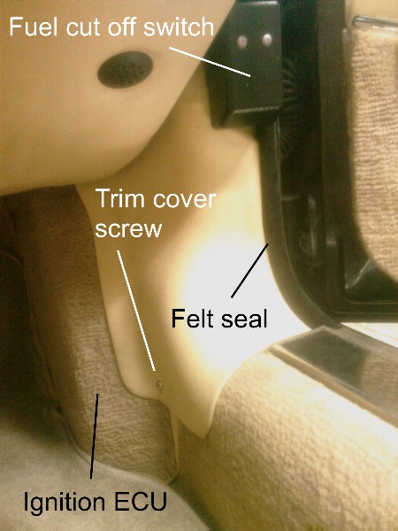
You need to wire into the central locking controller which on my US spec / lefthand drive 92 V12 is in the passenger / right hand A pillar. To get to it, working in the passenger footwell, remove the single screw holding the trim cover piece in place which is on the right hand side of the footwell. To remove this piece completely you have to remove the plastic cover from the fuel cut off switch and pull back the felt seal. Once that piece is removed you can then remove the single screw holding the Ignition ECU in place and move it out of the way (you don't need to disconnect it) See picture below.
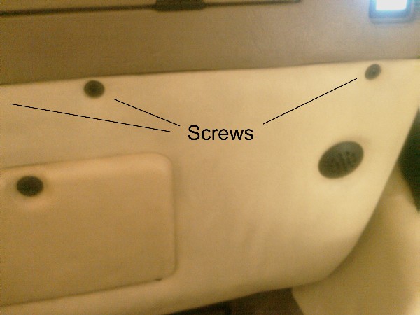
I chose to also remove the lower dash cover for ease of access. This cover is held in place by 3 screws at the front as shown below.
(There are maybe supposed to be more screws holding this cover on at the back, but on my car there were none)
The central locking controller is completely hidden from view INSIDE the A pillar. I chose to unscrew the 2 screws securing the controller inside the A pillar and remove the controller completely but if you have very small fingers you may be able to pull the connector off the bottom of the controller when it's still in place. There is just about enough room to pull the connector out of the A pillar so you can start making your wiring connections.
The bulldog kit offers a lot of extra functionality but I just wired it up for lock and unlock as thats all I needed. There is a large and rather poorly worded section in the bulldog instructions about how to work out what type of locks you have (positive, negative, reverse polarity). My 92 had negative polarity. Based on this negative polarity set up, wiring is as follows :
Function / Jaguar harness / Bulldog harness
+12V / Purple / Red
Ground / Black/Pink / Black AND Purple AND Purple/Black (yes, thats 3 wires to ground)
Lock* / Orange/Red / Green/Black
Unlock* / Orange/Blue / Blue/Black
Aerial / Yellow --> stretch this out under the dash and tape it in place
* I may have these 2 the wrong way round. If it unlocks when you press the lock button and vice versa, switch these 2 wires round. Sorry, didn't take good enough notes when I did it :-(
I then trimmed and isolated all of the extra wires from the bulldog unit and tie gripped it in place up above the fuse box, which is now visible as you have removed the lower dash cover.
Screw everything back together and spend the next 15 minutes locking and unlocking the doors via the remote until you flatten the battery :-)
Although there are not lights flashing or horns beeping when you lock and unlock, the lock motors themselves make quite a noise so its pretty easy from 10 feet away to hear them and know they've fired. Range with the remote is pretty good, 10 cars away across a car park type of thing.
Good clean fun for 40USD plus about 1 hour to fit it.
parking light output / brown/red (under the steering column) / white
horn / black/purple (under the steering column, in case you don't use the siren that comes with the kit) / brown
door trigger / black/purple (at the door switch) / green
trunk trigger / black/slate (right side, where harness connects to chassis) / blue
ignition / white/pink (under the steering column) / yellow
door unlock / orange/red (see @sarc's description) / blue
door lock / orange/blue / green
the kit comes with a starter relay that connects to the orange wire on the controller. I used it to trigger the fuel cut off switch.
for power I tapped into the horn power right at the fuse box (right side).
Glad you got it working too. I was considering adding an alarm but the car doesn't get out much and it rarely leaves my line of sight when it does.
I think I also have an easier way to do the locking now, and even more so an alarm....... there is a large mutliplug in the trunk, on the right hand side, behind the trim cover where the aerial is. This multiplug is there for the factory fitted security system option, which I think very few '92 cars actually have. Anyway, if you look at the wiring diagram for the security system, you will see you can control the door locks from here (same colour wires as you found in the passenger A post) You could also do starter inhibit and headlight flash from here, although you may need to add a few relays elsewhere in their original slots.
Another request - any pics of that off and back into where the module is? This is on my to do list but LOW on the list because I've heard it's a bear to get back in there.
This may be kind of silly to ask...
But I have an 1987 XJS.
Is it possible to do this to my car?
I have the feeling that it isn't...
Shouldn't be a problem. Your '87 should have the older system with Lucas lock solenoids and two relays---lock and unlock. A universal "remote lock" kit simply energizes the appropriate relay.
If you get a kit and post the specifics we should be able to walk you thru the install. I think I used one of the Bulldog kits on my '88 XJS. It was an easy installation.
I bought the same exact kit the first poster did.
I opened up the same stuff he did ... stared at it for a couple seconds, and put it all back together after realizing it is nearly impossible to know what you are looking at.
I don't know where the central locking controller is on an 87. It won't be in the same place as mine. The wiring is extremely simple..... you pull 1 wire to ground to unlock the doors, and pull another wire to ground to lock them again
@cadfael
It was pretty tricky to get to the central locking controller...... If I was doing it again I'd do it in the trunk
I've just finished installing my system in the trunk. It was very easy using the security multiplug. You go in to the trunk, right hand side, cover at the back underneath the aerial......
.......This cover is just stuck on using velcro fasteners..... just pull it open the you will see this......
(hopefully you don't actually see this many wires, because that means someone has been seriously messing with your car!)
The multiplug in the forefront of the picture is for the security system. On this connector you will get switched ignition, ground, unlock wire, lock wire, and control of interior lights. I took a permanent fused 12v supply off the battery, which is just round the corner. If I was going to do it again I would definitely go this route.
I actually bought a slightly different system this time.......
..... this cool little box has 4 relays, 2 are permanent switched, the other 2 are momentary. I used the 2 momentary ones for lock and unlock, and have used a permanent one to allow me to run the fuel pump remotely. I have been having major problems with fuel vapourization if the car is left sitting after a run and I am trying this out to see if it works...... I can walk up to the car, unlock it and start the fuel pump. Once I get in and put the key in and turn to ignition, the bulldogs power is cut off (by a relay) so there is no chance of the pump running on around the inertia switch in case of mishap. I've not had it in long enough to claim victory yet, but hopefully it will work
I don't know where the central locking controller is on an 87.
There isn't one...at least not in the same sense as the later cars.
Each door has a combination solenoid and controller unit. The solenoid portion obviously operates the mechanical linkage to lock/unlock the doors. The "controller" portion converts motion from turning the door key into an electrical pulse to energize the lock and unlock relays....which in turn operates the solenoids.
The lock relay is in the RH kick panel area. A 12v pulse from the aftermarket control unit to the orange/green wire at the lock relay will lock both doors.
The unlock relay is in the LH kick panel area. A 12v pulse from the aftermarket control unit to the orange/red wire at the unlock relay will unlock both doors.
Cheers
DD
I'm still a little confused.
1) On a 1987 XJS the lock/unlock relays be in the same location as the OPs?
2) You say here there is a unlock relay on the LH side and a lock relay on the RH side. To get my key-fob to completely function, would I need to get to both of these relays? Or would one be able to do both jobs?
Sorry for all the questions, I am as big a rookie as you could be...
I'm still a little confused.
1) On a 1987 XJS the lock/unlock relays be in the same location as the OPs?
As I recall the OP is dealing with a '92, which has door lock *motors* that are controlled by a solid state "controller"....and ECU for the locks, so to speak. There are no external relays.
Earlier cars, such as an '87, used Lucas door lock *solenoids* which are controlled by external relays, located as described above
The two systems are entirely different
2) You say here there is a unlock relay on the LH side and a lock relay on the RH side. To get my key-fob to completely function, would I need to get to both of these relays? Or would one be able to do both jobs?
Yes, you need to get to and use both relays for your installation
I too am trying to install an aftermarket kit into my '87 XJ-SC. I have followed Doug's advice and have the lock/unlock functions working, but would like to run the park light pulse to all indicator (turn signal) lamps.
Is there a simple way to do this? I have played with the hazard switch, flasher unit and indicator stalk but nothing seems to work.
Disclosure: I'm only two sips into my first cuppa coffee.
Pulsing all four signal lamps might get a little tricky. The 4-way hazard switch does this by mechanically joining the left and right circuits with a manual switch. I can't think of any way for your lock control module to accomplish the same thing
Pulsing the park lamps/side lamps/tail lamps would be a lot easier.
Your post made me rethink my approach and go back to basics. I was fixated by the hazard switch because it bypasses the ignition switch and is always live ... I don't need this as the keyless module provides the pulse of power!
The simple solution was to splice the keyless module power output wires to both the green/white (RH side) and green/red (LH side) wires on the turn signal switch. Hey ... it works! I probably could use the same coloured wires on the hazard switch but they are much harder to get at.
I was also hampered by "poor results" from my initial testing. I used a inline test light lead to take 12v power to the various wires. The test light would illuminate when I had a circuit, but not the turn signals. After the rethink, I used a solid wire and got the results I expected.
This wiring chart helped as it isolates the turn signal setup so is less confusing than the main wiring diagram.
Your post made me rethink my approach and go back to basics. I was fixated by the hazard switch because it bypasses the ignition switch and is always live ... I don't need this as the keyless module provides the pulse of power!
The simple solution was to splice the keyless module power output wires to both the green/white (RH side) and green/red (LH side) wires on the turn signal switch. Hey ... it works! I probably could use the same coloured wires on the hazard switch but they are much harder to get at.
I was also hampered by "poor results" from my initial testing. I used a inline test light lead to take 12v power to the various wires. The test light would illuminate when I had a circuit, but not illuminate the turn signals. After the rethink, I used a solid wire and got the results I expected.
This wiring chart helped as it isolates the turn signal setup so is less confusing than the main wiring diagram.
Hi, I am attempting fitting an aftermarket remote locking kit to my 85 XJS. The posts above are confusing as my car is older. If anyone of you responds to this I will post photos and more details. Fingers crossed !!!
thanks
i made that mod back 1994, parts car missing handles anyway! works fine, but open top i reach inside and open doors! no door handles reach inside and open.
cant remember what kit, annoying to change batteries in remote fob!
Amazingly the XJS didn't need any major surgery this weekend so I spent my time "upgrading" it slightly by adding remote locking. I have all of the electrical manuals which made the job easier but in case someone else wants to do this mod I though I'd write a few lines about how to do it.
You need to wire into the central locking controller which on my US spec / lefthand drive 92 V12 is in the passenger / right hand A pillar. To get to it, working in the passenger footwell, remove the single screw holding the trim cover piece in place which is on the right hand side of the footwell. To remove this piece completely you have to remove the plastic cover from the fuel cut off switch and pull back the felt seal. Once that piece is removed you can then remove the single screw holding the Ignition ECU in place and move it out of the way (you don't need to disconnect it) See picture below.
I chose to also remove the lower dash cover for ease of access. This cover is held in place by 3 screws at the front as shown below.
(There are maybe supposed to be more screws holding this cover on at the back, but on my car there were none)
The central locking controller is completely hidden from view INSIDE the A pillar. I chose to unscrew the 2 screws securing the controller inside the A pillar and remove the controller completely but if you have very small fingers you may be able to pull the connector off the bottom of the controller when it's still in place. There is just about enough room to pull the connector out of the A pillar so you can start making your wiring connections.
The bulldog kit offers a lot of extra functionality but I just wired it up for lock and unlock as thats all I needed. There is a large and rather poorly worded section in the bulldog instructions about how to work out what type of locks you have (positive, negative, reverse polarity). My 92 had negative polarity. Based on this negative polarity set up, wiring is as follows :
Function / Jaguar harness / Bulldog harness
+12V / Purple / Red
Ground / Black/Pink / Black AND Purple AND Purple/Black (yes, thats 3 wires to ground)
Lock* / Orange/Red / Green/Black
Unlock* / Orange/Blue / Blue/Black
Aerial / Yellow --> stretch this out under the dash and tape it in place
* I may have these 2 the wrong way round. If it unlocks when you press the lock button and vice versa, switch these 2 wires round. Sorry, didn't take good enough notes when I did it :-(
I then trimmed and isolated all of the extra wires from the bulldog unit and tie gripped it in place up above the fuse box, which is now visible as you have removed the lower dash cover.
Screw everything back together and spend the next 15 minutes locking and unlocking the doors via the remote until you flatten the battery :-)
Although there are not lights flashing or horns beeping when you lock and unlock, the lock motors themselves make quite a noise so its pretty easy from 10 feet away to hear them and know they've fired. Range with the remote is pretty good, 10 cars away across a car park type of thing.
Good clean fun for 40USD plus about 1 hour to fit it.
Would you know if this solves the problem of the door locks rapidly sequencing between lock/unlock in a 1994 xjs?