When you click on links to various merchants on this site and make a purchase, this can result in this site earning a commission. Affiliate programs and affiliations include, but are not limited to, the eBay Partner Network.
I do not know how familiar readers are with the inside of the pre facelift XJS instrument cluster, in particular the minor guages? The guages themselves are pretty reliable (being early examples of the air-cored type of guage, modern versions of which are used by Speedhut, according to their website). The problem lies in the way these guages are electrically connected to the flexible circuit board that is behind the nacelle.
My volt meter started playing up, and then the oil pressure guage, which is why I was and am, considering aftrmarket guages. As I have a brand new flexible board in stock, I decided to give the cluster a last chance; so I had the cluster apart last week and fitted the new flexible that I had in stock. After a bit of a struggle I had everything working except the oil pressure and volts guage; and these work when directly connected to my 12v source and respond properly to voltage changes.
However once mounted into the nacelle they do not, and the only reason I can see why not is the very iffy way they are connected to the flexible. Which is by tiny screws the threads of which need to bite into the copper strip of the instrument:
My new flexible circuit board, showing the holes through which the minor guage screws go, they secure the instrument and make the electrical contact
This shows the very tenuous way the circuit board makes electrical contact with the instrument
The screw, inserted through the flexible board has a very short contact length with the instrument board
Instrument inserted showing the very small contact point for the threads to make contact
I therefore decided to see if I could do better. My idea is to solder 3mm threaded rod to the instrument board and to poke that through the nacelle plastic so that a nut can secure the guage to the white plastic cluster chassis, and thus make a far more reliable connection. I tried using stainless rod but I found it is damn-near impossible to solder to stainless!
I therefore ordered brass threaded rod to try that. I have jigs all set up (unbelieveably of the four minor guages there are THREE different spacings!) so fingers crossed.
Jig for oil pressure guage board with clamping block to hold it in position during soldering, in place
Three different fixing screw spacings
Jig closeup
New flexible but with the minor guages still with their screw contact to the guage board
Mockup showing how the threaded rod soldered to the guage board will contact the flexible more reliably, I hope.
So yesterday and today I got to it. I have a spare cluster so trial fitting the instrument boards was easy, as was making the jigs, as the spare cluster could be used as a template. I found that the brass rod needed to be 26mm long, and have the soldered end flattened off so it resisted turning in the solder:
26mm long for the outer fixings, the middle contact used in three of the guages needs to be shorter, once soldered it can foul the plastic protrusions so these were removed, see pic further below
End flattened off to fix into the solder better
Soldered instrument boards. These are fixed to the actual guages by 8mm nuts and are easily removed for soldering:
Board attached to guage
Board removed for soldering
Trial fitted to chassis, note shorter central rod
Ready to solder
An advantage of the brass rod is that it is easy to bend slightly so as to line up the rods with the chassis holes. Even so, I opened up the chassis holes to 3.5mm from 3mm to give a bit more play. You need 10mm of rod showing through the chassis to get the nut on easily. Additionally, because the threaded rod holds the guages securely, and to make the soldered parts easier to get properly home in their slots, using pliers I pinched off the plastic sticking up from the chassis:
Plastic protrusions pinched off for easier fitting of the soldered board
The soldered boards were trial fitted in the spare chassis and are ready to go into the car nacelle:
All ready to be fitted, dreadful soldering hidden!
The guages in the car nacelle were removed and their boards swapped for the soldered ones. Then refitted as in this photo:
Threaded rod and nuts now holding the guages.
Just in case, tape over the fixings.
All went back in the car and the oil pressure and volts guages started to work properly and the other two continued to work. Poor connections to the guages are a known weak spot that the Great Palm discusses in The Book. I think that this modification is reasonably permanent, electrically more reliable, and what is more, in the event of any further trouble, it is easy to troubleshoot, disassemble and fix.
Last edited by Greg in France; Apr 24, 2026 at 12:12 AM.
Thank you Grant, and Paul.
I think it would be worth my pointing out my underlying motivation in all my work on the car.
The XJS, unlike so many classic cars, is still 100% up to snuff in modern traffic conditions, as well as being the best GT car I have ever been in, let alone owned. As far as my petrol pocket-money allows, it is treated as a daily driver, at least when dry in the winter and in other seasons all the time. I am far more concerned about reliability and serviceability than I am about originality; hence my better diff, simplified cooling system, electric fans and their redundant circuitry, and other small changes (eg. kickdown switch, TPS setting mod, better hot starting, etc etc) that have all gone to make the car more reliable and useable.
While obviously everyone on the forum will understand the inability of an owner to live with non-functioning dash guages, making them inherently better connected, rather than just making them work for a bit (as I have done before) is what makes me have the patience required! That is my motivation, to keep the car dead right and as inherently reliable and easy to repair and understand, as possible.
Last edited by Greg in France; Apr 24, 2026 at 05:42 AM.
Greg, you raise an interesting point, and I think I'm in the same boat. At least we have similar goals. This is what is leading me to considering a Mobeck system, though I'd like to hear more feedback on that. I've considered electric fans, but here I am hampered by my faith in my ability to correctly install the electronics. I'm also still considering differential mods, especially if I ever do install that five-speed. Now you have me thinking I need to find a pre-facelift cluster that someone is parting out, just so I can install all these mods, as well as perhaps change the speedometer from one that picks up at the differential to one that picks up from the transmission (no interest in a GPS speedo). Then I can find 3.33 gears for the diff, and...
Yeah, the list goes on. First, I need to rebuild my steering rack. SNG says parts are on the way, so...
Mate what a great job! I have to remove the dash on my '88 V12 as I need to get to the HVAC. I shall study your description and see whether I am capable of doing what you have done. Electrics are not my favourite things to work on. ATM I have the engine and gearbox, Front & rears out - I have those re-built and moving onto the motor.
Anytime you find a solution to a problem most people simply live with. Because they lack the patience, skill, or just the, Damn It I ain't giving up! Determination. I' say that's a good days work.
I'd like to hear more feedback on that. I've considered electric fans, but here I am hampered by my faith in my ability to correctly install the electronics. .
Good luck with all your work!
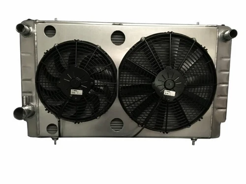
Honestly, electric fans are not hard to do; but planning is needed. The most difficult thing is installing them physically into the space. I managed it after lots of poor attempts; but I now know the best idea BY FAR is to buy a new ally rad with the fans part of it, such as this:
Not cheap but this particular make (Roose motorsport in the UK) uses SPAL fans which are the only ones in the aftermarket up to the job.
The next part is controlling them. Forget the proprietory contollers, they give up in no time under the V12 bonnet conditions. In fact, every single non-OEM electronic under-bonnet part I have ever tried has failed. Grant Francis has invented BY FAR the best solution. Essentially one fan is wired to be on all the time with the aircon compressor. The other one is temperature switched via a relay, using the OEM temperature switch in the water pump inlet. The relays are fed from the firewall positive post. If you ever want to do it I will be happy to PM you wiring details. I also incorporated a cabin switch for it as a backup.
Thank you Greg. I will take you up on that. Agreed on the SPALs. First thing that comes to mind (sunk cost theory) is I spent a lot on a Wizard Aluminium rad not long ago, so another radiator may not be the best way to go. I must think on the mounting.
It is time to "update" the car overall. Next winter's project list is getting longer...
Thank you Greg. I will take you up on that. Agreed on the SPALs. First thing that comes to mind (sunk cost theory) is I spent a lot on a Wizard Aluminium rad not long ago, so another radiator may not be the best way to go. I must think on the mounting.
In the end I welded horizontal studs pointing rearwards on the cross member under the rad, then I ditched the rad top panel and replaced it with a strut to hold the fans and a separate one to hold the rad, condenser and dryer. I have not got access to my photos this week, but if you are interested I will post a photo when I get back.
The fans have vertical struts top and bottom which attach to the studs below and the strut above. This is the best way I could come up with, as like you, I had bought an ally rad without the fan cowling attached. Silly me.
Thiis a starter for the Efan program I wrote a long time ago.
Those Ford fans are NLA from Ford, and the knockoffs are crap at best. The OE Ford ran Bosch Germany fan motors.
People I have talked with on this mentioned LOTS of cars have Efans, sonce then, and a walk aroung a wrecking yard with a tape ,easure and an open mind, could be a clue, Hyundai, Toyota, etc etc. Used fans a CAUTION, but they may sew a seed for later.
I have a Mud map, and I mean MUD map sketch of the wiring somewhere in here. I will post it when I find it. Greg mai have a better "map" when he surfaces.
Edit: Found the Mud Map, now attached.
When the time comes I suggest a NEW thread, as this is getting a little OFF Gregs awesome OE Post. Norri can move this to that thread when needed.
Since its not urgent, enjoy a beer or 3.
Last edited by Grant Francis; Apr 26, 2026 at 04:06 AM.
I took the 4.0 out today for Drive-It Day in the UK (Everyone takes their classic car out to show solidity to the Classic car movement and raise money for charity). Drove to Headcorn aerro drome with 1000+ cars from Mins to McLarens.
And all my minor gauges performed perfectly, from voltmeter matching the figures on my cigarette leighter meter, to temp, oi & fuel gauge! Clearly a fully-charged battery and a good clean of the wheels has worked wonders!
Are the instruments on the facelifts connected the same way? (Not to in any way suggest your shine and polish is not the best way to ensure accurate instruments!).
Fantastic turnout though. Sadly this sort of gathering does not happen in France.,
Good luck with the steering rack. I tried to do it on my 90...2 times, including with advice from an expert at Maval Industries in Ohio...and failed to get the seals correct. I sent it off them and he rebuilt the rack and power steering pump for me correctly, and has worked perfectly since.
The Brits use the term 'brilliant' to mean 'not too bad', but in the description of your work here, 'brilliant' means brilliant. Thanks for the detail.
Last edited by 3Jagsplusothers; Apr 27, 2026 at 07:18 AM.
Reason: Associate the comment with the thread starter