When you click on links to various merchants on this site and make a purchase, this can result in this site earning a commission. Affiliate programs and affiliations include, but are not limited to, the eBay Partner Network.
I know this gets asked quite a bit but I recently bought an xjs that was a barn find. Turns over nicely, but no spark at plugs. Pulled the lead from the primary coil to the distributor cap and checked for spark, nothing but about 10-12v. Checked power to the coil which is 12v ignition on dropping to 9ish while cranking.
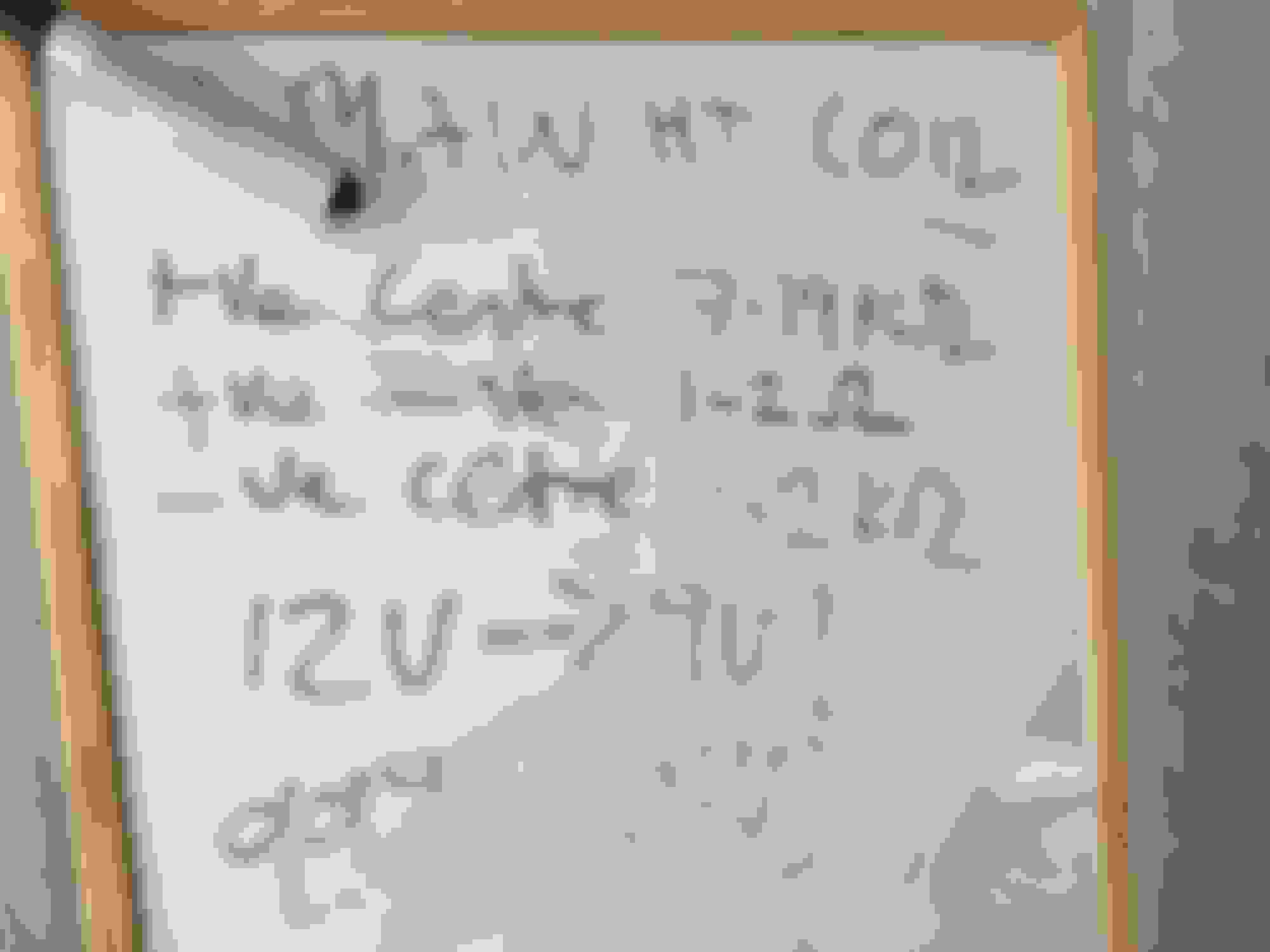
Ht coil looks pretty new, could it be this or something further up? Measured coil resistances as can be seen in photo. It's a Lucas ignition system.
Any ideas? More used to mechanical than electrical.
That 1.2ohm is OK as long as ALL the wires were unplugged from that coil BEFORE testing.
Each coil is rated at 1.2ohm and when connected as they are read 0.6ohm approx.
The less than battery volts when ign is ON is NOT ACCEPTABLE. The drop to 9v when cranking will NEVER start that engine.
The fact there is NO spark has a VERY LONG list indeed.
Some of which are:
GM module inside the ignition amp (lh inlet manifold top) is fried, common.
The 2 coils are mis-wired. as in NOT +ve to +ve, and -ve to -ve. Not so common, but I have seen it.
Battery +ve cable path is DIRTY. There is a connector on the LH firewall, then another on the RH firewall. These must be CLEAN and tight.
Earth straps/connectors, and there a MANY, are dirty/grubby/broken, and this is COMMON.
The 2 wires that exit the distributor at the front break, then there is no pulse to that amp, and thus no spark. The breakage is rather common INSIDE that rubber bung in the distributor casing.
I would recheck the 2 coils ohm readings with NOTHING connected at all. PLEASE mark those wires BEFORE disconnecting. Then reconnect that 2nd coil as above, and do the +ve to -ve ohm reading again.
I am leaning towards an ign module.
I also realise you are trying to get it running, but that wiring is very ordinary, and that alone will reek havoc.
What is the trigger for the ht coil in the distributor? I've got two wires come out the front, will it be a hall sensor, optical sensor or a set of contacts? Best way to check for a wire break?
Also is there a way to test the Lucas box on the inlet manifold?
And any chance of a photo of the +ve and -ve connections on the firewall?
Thanks for your help
Hall effect system.
Broken wires. The ONLY way is to unplug the wires AT the connector near #3B spark plug, remove the dizzy cap, ohm meter the wires end for end, and WIGGLE them around. They can be a fair MONGREL to find a break in. I have found breaks inside the rubber bung, and also the 2 wires INSIDE the distributor.
NO snaps of those 2 +ve posts at the firewall, easily found, the LH is near the heater hoses, the RH is in the MIRROR position on the other side. They are BOTH battery HOT, so if the battery is still connected DO NOT FIDDLE WITH THEM. They originally have a rubber protection cap over them.
Ign amp test, NOPE. Not that I know of. The modules are flaky sometimes, BUT, read the next thing on the menu.
I forgot last night, you will do the same when your this old, and have spent the thousands of hours with the mighty V12 that I have.
INSIDE that amp is a condensor, simple litlle sucker, that was originally a noise suppressor???, and it is connected to the +ve of the module, and it leaks to earth now that its OLD. REMOVE it, and maybe you will have spark.
DO NOT disconnect the Zenor diode by mistake. It is an obvious item when you open the amp, as it is imbedded in the case.
That condensor is held in place with a simple PK screw, and is exactly the same as a condensor in a "points system" distributor. Removing this thing has woken a few dead V12's for me over the years. It is NOT needed. The Poms did some strange stuff in the early days.
Last edited by Grant Francis; May 9, 2016 at 09:39 PM.
Minor technical correction, according to repair operation manual p 86-9 (Constant energy ignition)
It doesn't use a Hall effect sensor.
"A voltage signal generated by the reluctor and pick up assembly is interpreted by the amplifier that switches on and off current flowing in the primary winding of the HT coils. When a reluctor tooth passes across the pick up limb the magnetic field strength around the pick up winding is intensified creating a voltage in the winding. The rise and fall of this voltage is sensed by the amplifier and is used to trigger the output of the transistorised amplifier"
Fault finding:
Test 3
With ignition switched on the voltage at the positive terminal of the main coil should be 12V. If voltage below 11V check wiring to and from ignition switch.
Test 4
Disconnect leads from negative terminal of main coil. With ignition switched on a 12V reading should be obtained from the negative terminal.
A zero reading would indicate a faulty main coil. If a 12V reading is obtained, reconnect the disconnected leads to the main coil and repeat test 3 and 4 at the auxiliary coil.
Test 5
Disconnect distributor pick up leads from the amplifier. Measure the resistance of the distributor pick up. It should be 2.2 to 4.8K ohms. An incorrect reading indicates a faulty pick up coil.
Test 6
Connect a voltmeter between the positive terminal of the battery and the negative terminal of the main coil. Switch on the ignition and the voltmeter should indicate a zero reading.
Crank the engine and the voltmeter reading should rise to between 2 and 3 volts . If the voltmeter reading remains at the amplifier is suspect.