When you click on links to various merchants on this site and make a purchase, this can result in this site earning a commission. Affiliate programs and affiliations include, but are not limited to, the eBay Partner Network.
have a 2007 xk ragtop. Third brake light located on spoiler is out. Is there a fuse for this. My understanding that it is LED assembly. Would all bulbs burn out at once. Also understand that I should get an indicator in the message center that light is out, is this true? How do you remove the unit for changing? Any help would be appreciated. Light appears to have stopped working after dealer replaced the battery, any connection possible?
Here is the procedure to remove third brake light assy. I hope this will help.
Exterior Lighting - High Mounted Stoplamp
Removal and Installation
Removal
1. Remove the liftgate lower trim panel.
For additional information, refer to: Liftgate Lower Trim Panel (501-05 Interior Trim and Ornamentation, Removal and Installation).
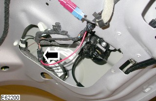
2. Disconnect the high mounted stoplamp electrical connector.
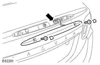
3. Remove the high mounted stoplamp.
Carefully release the Torx bolt covers.
Remove the 2 Torx bolts.
Installation
1. Install the high mounted stoplamp.
Tighten the Torx bolts to 6 Nm (4 lb.ft).
Install the Torx bolt covers.
2. Connect the high mounted stoplamp electrical connector.
3. Install the liftgate lower trim panel.
For additional information, refer to: Liftgate Lower Trim Panel (501-05 Interior Trim and Ornamentation, Removal and Installation).
I find it hard to believe the 3rd brake light would fail so soon...and right after a battery replacement? My guess is on a blown fuse, or a wire pulled from a harness.
The LED's can burn out individually, so all at once points to either an over voltage, or primary short in supply. The battery replacement sounds probable, though no shop will admit to that!
Just a quick caution - I found this out while retrofitting LEDs to inboard tail lamps. The current drive on connector CA129-pin 9 (that is the currrent drive for the CHMSL) is an output from the Aux Junction Box between rear seats.
This circuit is not fused, as it uses a CMOS overcurrent detection that "crowbars" the output and holds it to zero to prevent damage to current driver circuit in the case of a short.
So, it may look as though CHMSL is dead (all LEDS out), but it is because you have no output from CA129-9.
The only way I have found to reset the output is to disconnect positive battery terminal for 30 seconds....when you hook it back up, waalaa, CHMSL lights back up.
Success getting my 3rd brake lamp working again today.
Previously, I made sure that all wiring and connections were solid. Then I disconnected the battery to reset the ECU. None of those were the solution. So, I bought a replacement unit from Gaudin for a very reasonable price.
Removal and installation is a straightforward process (thanks to georgekale). However, the torx screws are "tamper resistant". So, unless you already have some or don't mind a second trip to the auto parts shop - go ahead and get a set of tamper resistant torx bits. The bit needed is a T-20.
This forum is great - I hope I can contribute back a little.
Hello...this post refers to "Liftgate Lower Trim Panel (501-05 Interior Trim and Ornamentation, Removal and Installation)". It appears to be a link and when I click on it I get a 'user denied' message (and I am signed on to this site). I could use this information if you can supply it. Thanks...Mark
Hello...this post refers to "Liftgate Lower Trim Panel (501-05 Interior Trim and Ornamentation, Removal and Installation)". It appears to be a link and when I click on it I get a 'user denied' message (and I am signed on to this site). I could use this information if you can supply it. Thanks...Mark
I have just changed my high level brakelight on my Coupe as several LEDs had gone. ( The dealer was in denial because his plug in tool said it was still working and he couldn't be bothered to get out and look!) With the Coupe you just need to pull off the lowest couple of right hand poppers on the inside trim to access the connector. The security screws on the brakelight are torx pin head and yes you really need to look and check you have one before you start.
my torx do not fit these with a tiny pin in the middle. What tool do I need?
I found it so funny, that somebody comes up with a 'security' torx design (let's keep people from removing our stuff), and the thieves were probably buying the bits 5 minutes later.
I found it so funny, that somebody comes up with a 'security' torx design (let's keep people from removing our stuff), and the thieves were probably buying the bits 5 minutes later.
So true... or I found out , just use a small flathead, if the torque is not too tight.
I found it so funny, that somebody comes up with a 'security' torx design (let's keep people from removing our stuff), and the thieves were probably buying the bits 5 minutes later.
When these came to being nobody had the right tools to defeat them but the tool industry soon caught up. The fastener that also came at the same time was the double head one where when you tightened it to required torque the head would break off and leave a smooth flat surface. These needed to be drilled out and they were a PITA.
Got the secure torx out fine, but now how do I remove the grommet that hold the wires ? Very hard to access but I guess you just work it out from either top or bottom?
Some electronic information on the 3rd brake light
Some time ago, I had repaired the "Suppression stop light High Mounted" in my 2010 X150 Convertible, which is basically an electronic circuit to filter board electronics peaks from the LED center brake light (a.k.a. "Lamp-high mounted stop").
The workshop manual (2010 MY onwards) shows the following diagram:
3rd brake light circuit X150 2010 onwards
The above is just a schematic representation of the actual circuit. In reality, the "Suppression stop light high mounted" circuit is as follows:
Power supply (+12V) from the "Junction box-auxiliary" goes via the supply cable in the boot lid (convertibles only!) into the filter circuit board ("rot +").
The +12V input goes through a double diode (originally: a surface mounted double diode)
The output of the diode goes via a very light resistor (ca. 1-2 Ohm) to the + supply towards the LED brake light module ("+ rot")
The return ("sw.") from the LED brake light module is fed via another very light resistor (ca. 1-2 Ohm) into the ground rail ("- schwarz -") of the circuit board towards the supply cable in the boot lid (convertibles only!)
The output of the diode is also fed into the ca 220 Mu capacitor towards the ground rail ("- schwarz -") on the circuit board. This capacitor serves to filter out any peaks and any AC components of the power supply voltage
In addition, there is one high resistive set of 2 resistors of each ca. 5 Mega Ohm in series, connecting the +12V input to the ground rail on the circuit board
In addition, there is another high resistive set of 2 resistors of each ca. 5 Mega Ohm in series, connecting the + of the capacitor to the ground rail on the circuit board
You can determine this circuit from the picture below. Note that I already tweaked the originally double diode: more on this further below.
The LED brake light module indicates to allow 13.5 Volt as input, so it can easily be tested by supplying +12 Volt to the red cable with the black cable connected to ground.
In theory, the entire filter could be omitted and the LED brake light module would work straight from its +12V cable.
However, as others reported also, the "Junction box-auxiliary" has a light functioning check to disconnect any power supply when the LED light would fail. It seems most likely to me that the above complex circuit would switch off the brake light if anything non-standard would happen to the whole circuitry
So here we have the theory. Now follows some of my experience in repairing the 3rd brake light:
Originally, the double diode had failed: It did not pass any power onwards to the circuit.
I replaced this double diode by a higher current single diode (e.g. N4004).
To do this: scratch away some of the protective paint on both the +12V supply rail and the + entry rail to the 240 Mu capacitor, and solder the diode in correct orientation to the rails:
Originally, the replacement of the diode worked and solved my original issue.
However, recently, the 3rd brake light failed again on me. I found some intermittent contact when supplying +12V to the cable assembly.
I found several issues:
the supply voltage from the auxiliary junction box to the 3rd brake light, remained constant at ca. 6 Volt, regardless whether the brake pedal was pressed or not.
the diode got loose from the circuit board after some jiggling
the high resistive resistors were not passing any current
bad contacts in the connection towards the LED light module
To get back stability in the cabling, I did the following:
after checking its functioning (otherwise: replace!), resolder the diode to the suppression circuit board as explained above
touch each of the connection cable ends with a bit of additional solder to ensure their proper contact
touch each end of each of the 6 resistors with a bit of additional solder to ensure their proper contact
clean all contacts of connectors using contact spray
bend the pins from the LED light module connector slightly to ensure their constant contact with the counter-connector to the suppression circuit
close up the suppression circuit cover/isolation and seal it fully by enrolling it with electrical isolation tape
After this, my 3rd brake did not yet function in the car, so I still have to do one additional action to restore power to the 3rd brake light:
reset the Auxiliary junction box by disconnecting the battery for some minutes and reconnect it.
Well I found a brand new rear brake light, genuine Jaguar part as some of my LED�s were no longer working. After reading this post I removed the trim and removed the old unit, it�s fiddly but doable. However the new unit came with lovely brand new torx screws but the captive nut (steel) has corroded and fell to bits! So I no longer have anything to bolt either the old or new unit back into, I think the technical description is cleat or clinchnut. I don�t suppose anyone has a part number or an idea for me?I can�t simply put a nut on the back of the screw as it would just spin when tightening, also the hole or gap where the nut would go is too large!!
Not sure as JPART does not list that separately from the entire 3rd light assembly.
But I did find a "Flange Nut" from the rear tail lights? With what's left of yours it's hard to tell?
It's listed as an M5 thread. #C2Z3613 but I think it's just a plain nut and not some sort of clip?
Can you post a picture of the back of the light?
.
.
.