
CATS with a switch

Thread Starter
|
Veteran Member
Joined: Jan 2012
Posts: 2,953
Likes: 1,120
From: Phoenix, AZ USA
UPDATE: There are a couple of failed attempts documented in this thread but the real solution is in post #33
The name is kind of silly but I do like the idea of adaptive suspension. Problem is that it doesn't react fast enough. By the time I toss her into a corner and the accelerometer reacts, I have already sloshed to one side of the car. Once it is in firm mode all is well but it just doesn't get there soon enough, so I was thinking that a switch to choose the mode would be nice to have.
I haven't investigated this and don't really know what it might take but I thought I would ask if anyone had added a toggle switch to the CATS system.
I imagine that the suspension is a 12v solenoid and was thinking that I could toggle it with an external switch. Even better would be to use the "S" switch for the transmission in conjunction with a relay to toggle the firm setting.
Has anyone tried something like this?
Last edited by ccfulton; Nov 17, 2012 at 09:14 AM.
Veteran Member


Joined: Apr 2010
Posts: 7,657
Likes: 3,019
From: Arlington VA USA
The name is kind of silly but I do like the idea of adaptive suspension. Problem is that it doesn't react fast enough. By the time I toss her into a corner and the accelerometer reacts, I have already sloshed to one side of the car. Once it is in firm mode all is well but it just doesn't get there soon enough, so I was thinking that a switch to choose the mode would be nice to have.
I haven't investigated this and don't really know what it might take but I thought I would ask if anyone had added a toggle switch to the CATS system.
I imagine that the suspension is a 12v solenoid and was thinking that I could toggle it with an external switch. Even better would be to use the "S" switch for the transmission in conjunction with a relay to toggle the firm setting.
Has anyone tried something like this?
It it looks like it could be done with a switch and relays. The solenoid in each of the four shocks would need to be controlled.
The 'S" switch has a contact that switches to ground (not sure offhand if itis NO or NC). It has fairly light duty contacts, so it probably would need a simple transistor driver to drive the four relays.
Most of this can be gleaned from the Chassis and Transmission sections of the circuit diagram.
Thread Starter
|
Veteran Member
Joined: Jan 2012
Posts: 2,953
Likes: 1,120
From: Phoenix, AZ USA
Do you know If the CATS module has any feedback mechanism from the solenoid that it monitors? My concern being that applying the actuation voltage from outside the module might cause a fault if it checks the current draw or continuity to monitor solenoid health.
I haven't tried this but does the system show a fault if a solenoid is disconnected? I heard there have been some who replaced the shocks and struts with non active ones and if this doesn't cause any faults then maybe this will be fairly simple.
Another option might be to toggle one of the sensor inputs. I believe I read somewhere that putting on the brakes sets the firm mode to reduce dive but could also see how that might confuse other things like the cruise control if they are tied together at the brake switch.
Any idea what the accelerometer sensor output looks like?
I may have a new weekend project.
Veteran Member
Joined: Apr 2010
Posts: 7,657
Likes: 3,019
From: Arlington VA USA
Do you know If the CATS module has any feedback mechanism from the solenoid that it monitors? My concern being that applying the actuation voltage from outside the module might cause a fault if it checks the current draw or continuity to monitor solenoid health.
I haven't tried this but does the system show a fault if a solenoid is disconnected? I heard there have been some who replaced the shocks and struts with non active ones and if this doesn't cause any faults then maybe this will be fairly simple.
Another option might be to toggle one of the sensor inputs. I believe I read somewhere that putting on the brakes sets the firm mode to reduce dive but could also see how that might confuse other things like the cruise control if they are tied together at the brake switch.
Any idea what the accelerometer sensor output looks like?
I may have a new weekend project.
I haven't tried this but does the system show a fault if a solenoid is disconnected? I heard there have been some who replaced the shocks and struts with non active ones and if this doesn't cause any faults then maybe this will be fairly simple.
Another option might be to toggle one of the sensor inputs. I believe I read somewhere that putting on the brakes sets the firm mode to reduce dive but could also see how that might confuse other things like the cruise control if they are tied together at the brake switch.
Any idea what the accelerometer sensor output looks like?
I may have a new weekend project.
There is no obvious feedback mechanism. Many of the modules monitor for open or short coil faults however. If this is the case, you should be able to fake it out with a resistor that is equivalent to the solenoid coil resistance.
The 3 acclerometers appear to be analog signals. There is also a brake and speed input into the controller. Description is attached.
Senior Member
Joined: Nov 2009
Posts: 753
Likes: 220
From: New York state
Charlie - my thinking is exactly the same as yours - the system is too slow to react. I want to be able to leave the system in the firm setting for "spirited" driving, as you can do with any modern electronic suspension.
I know that the system defaults to the firm setting if the adaptive module looses power or detects a problem. Each shock is monitored by the module so unplugging a shock will then set the system into default. So I placed a toggle switch into the left front shock to see if this would work.
It works but the problem is it does not instantly go into default and once it does it won't instantly return to to auto when I restore the shock circuit. The module is sampling the shocks to slowly
With the help of WhiteXKR, ou and others I know we can find a solution to this.
Last edited by rocklandjag; May 18, 2012 at 10:27 PM.
Veteran Member
Joined: Apr 2010
Posts: 7,657
Likes: 3,019
From: Arlington VA USA
Charlie - my thining is exactly the same as yours - the system is too slow to react. I want to be able to leave the system in the firm setting for "spirited" driving, as you can do with any modern electronic suspension.
I know that the system defaults to the firm setting if the asaptive module looses power or detects a problem. Each shock is monitored by the module so unplugging a shock will then set the system into default. So I placed a toggle switch into the left front shock to see if this would work.
It works but the problem is it does not instantly go into default and once it does it won't instantly return to to auto when I restore the shock circuit. The module is sampling the shocks to slowly
With the help of WhiteXKR, ou and others I know we can find a solution to this.
Direct control should be better. Typicaly controller software gives real time control considerable priority over fault detection.
Senior Member
Joined: Nov 2009
Posts: 753
Likes: 220
From: New York state
Would it work if I interrupted line voltage to the one of the accelerometers or if I short 2 wires together on one of the accelerometers. I would use a toggle switch in either case
thanks you for your help,
Ed
Trending Topics
Veteran Member
Joined: Apr 2010
Posts: 7,657
Likes: 3,019
From: Arlington VA USA
I really do not know...it will take some experimentation if you want to use the controller instead of directly switching power to the solenoids. You also might find that the major delay is in the controller and not the accelerometer....it remains to be seen.
Thread Starter
|
Veteran Member
Joined: Jan 2012
Posts: 2,953
Likes: 1,120
From: Phoenix, AZ USA
Experiment #1: Try faking an accelerometer signal to the trick the controller into firm mode
The controller supplies the accelerometers with a GND and a +5V and the output from the accelerometer can range between those two values. At 1G the vertical accelerometer reads 2.5V.
At a high enough acceleration the controller sets the firm mode so my thought was to connect the +5 supply to the sensor input to the controller so that it always read high.

No errors on startup but got a suspension fault after driving a short distance. Can't say as I'm surprised really, if I had made this control I would probably have checked for nonsense and stuck values too.
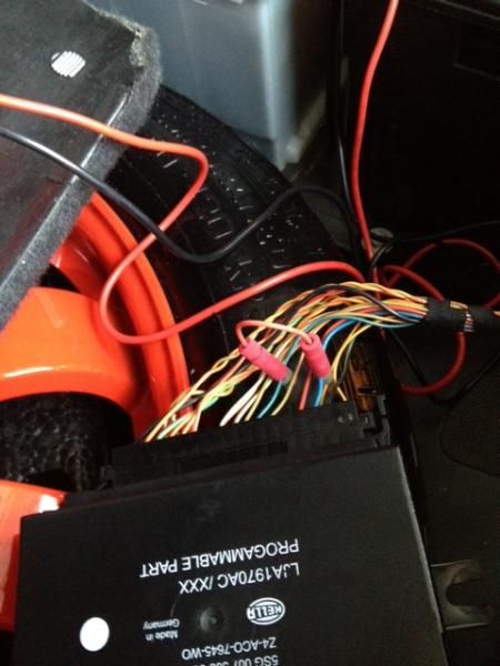
Anyway, it looks like tricking the inputs to the control isn't going to work and it is going to take driving the solenoids directly. I measured them through the harness from the connector at the control and got 7.2 ohms.
Next test will be to build up something to disconnect the solenoids and switch in a matching load so that the controller doesn't know the difference.
The controller supplies the accelerometers with a GND and a +5V and the output from the accelerometer can range between those two values. At 1G the vertical accelerometer reads 2.5V.
At a high enough acceleration the controller sets the firm mode so my thought was to connect the +5 supply to the sensor input to the controller so that it always read high.
No errors on startup but got a suspension fault after driving a short distance. Can't say as I'm surprised really, if I had made this control I would probably have checked for nonsense and stuck values too.
Anyway, it looks like tricking the inputs to the control isn't going to work and it is going to take driving the solenoids directly. I measured them through the harness from the connector at the control and got 7.2 ohms.
Next test will be to build up something to disconnect the solenoids and switch in a matching load so that the controller doesn't know the difference.
Thread Starter
|
Veteran Member
Joined: Jan 2012
Posts: 2,953
Likes: 1,120
From: Phoenix, AZ USA
Not all have it. Easiest way is to tell is to open the bonnet and look at the top of the front struts. If there is a wire running to them then you have the active system.
Thread Starter
|
Veteran Member
Joined: Jan 2012
Posts: 2,953
Likes: 1,120
From: Phoenix, AZ USA
Experiment #2
After #1 failed, I was thinking about why and it could be that +5V is considered an invalid input since the accelerometer could never actually output that signal. Or it could be that the controller is comparing the two vertical accelerometers and thinking that something is fishy that one of them is showing a large acceleration and the other is not.
The thought went that if the voltage were somewhat less than 5V and was applied to the lateral accelerometer then the above two conditions could be avoided.
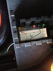
I made a voltage divider out of two 56ohm resistors and connected it between the +5V and GND. Total current through this would be <50mA, which should be pretty safe. Tapped the center to get 2.5V for the input to he accelerometer signal. The nominal signal from the lateral sensor is 1.5V so I imagine that 2.5 is enough to trigger firm mode and it is well below the maximum possible output from the sensor.
Built it up with a breadboard for testing.
No errors on start up and after driving around a bit, seat of the pants feel says that it is in firm mode.
Anyone know how to check this for sure? If I had AutoEnginuity or something similar I imagine I could just ask the controller, but barring that, how could I tell for sure while the car is moving, since this is the only time it goes into soft mode?
I'll run this for a few days to make sure there are no adverse effects, but so far so good.
After #1 failed, I was thinking about why and it could be that +5V is considered an invalid input since the accelerometer could never actually output that signal. Or it could be that the controller is comparing the two vertical accelerometers and thinking that something is fishy that one of them is showing a large acceleration and the other is not.
The thought went that if the voltage were somewhat less than 5V and was applied to the lateral accelerometer then the above two conditions could be avoided.
I made a voltage divider out of two 56ohm resistors and connected it between the +5V and GND. Total current through this would be <50mA, which should be pretty safe. Tapped the center to get 2.5V for the input to he accelerometer signal. The nominal signal from the lateral sensor is 1.5V so I imagine that 2.5 is enough to trigger firm mode and it is well below the maximum possible output from the sensor.
Built it up with a breadboard for testing.
No errors on start up and after driving around a bit, seat of the pants feel says that it is in firm mode.
Anyone know how to check this for sure? If I had AutoEnginuity or something similar I imagine I could just ask the controller, but barring that, how could I tell for sure while the car is moving, since this is the only time it goes into soft mode?
I'll run this for a few days to make sure there are no adverse effects, but so far so good.
Senior Member
Joined: Nov 2009
Posts: 753
Likes: 220
From: New York state
Experiment #2
After #1 failed, I was thinking about why and it could be that +5V is considered an invalid input since the accelerometer could never actually output that signal. Or it could be that the controller is comparing the two vertical accelerometers and thinking that something is fishy that one of them is showing a large acceleration and the other is not.
The thought went that if the voltage were somewhat less than 5V and was applied to the lateral accelerometer then the above two conditions could be avoided.
I made a voltage divider out of two 56ohm resistors and connected it between the +5V and GND. Total current through this would be <50mA, which should be pretty safe. Tapped the center to get 2.5V for the input to he accelerometer signal. The nominal signal from the lateral sensor is 1.5V so I imagine that 2.5 is enough to trigger firm mode and it is well below the maximum possible output from the sensor.
Built it up with a breadboard for testing.
Attachment 19640
No errors on start up and after driving around a bit, seat of the pants feel says that it is in firm mode.
Anyone know how to check this for sure? If I had AutoEnginuity or something similar I imagine I could just ask the controller, but barring that, how could I tell for sure while the car is moving, since this is the only time it goes into soft mode?
I'll run this for a few days to make sure there are no adverse effects, but so far so good.
Could you tell me more about how to build the circuit that you created to trick the accelerometer?
thanks
Thread Starter
|
Veteran Member
Joined: Jan 2012
Posts: 2,953
Likes: 1,120
From: Phoenix, AZ USA
I think it was an option, although I'm not sure of a way to tell if it's installed other than to pop the hood and confirm the wire running to the strut.
Senior Member
Joined: Nov 2009
Posts: 753
Likes: 220
From: New York state
This weekend I am going to connect my left front shock to a voltmeter inside the car and to see when the shock goes into the firm setting. I already have wires from the enigne compartment thru the bulkhead.
On the XJ8's the module is way up under the right side of the passenger footwell and very difficult to get to the wires. It is easier to get to the shock and accelerometers. You have it much easier in the XK.
Can I purchase a tap board like you used at Radio Shack?
thanks
On the XJ8's the module is way up under the right side of the passenger footwell and very difficult to get to the wires. It is easier to get to the shock and accelerometers. You have it much easier in the XK.
Can I purchase a tap board like you used at Radio Shack?
thanks
Thread Starter
|
Veteran Member
Joined: Jan 2012
Posts: 2,953
Likes: 1,120
From: Phoenix, AZ USA
I think Radio Shack still sells breadboards but this particular one came from Frys electronics.
Next step for me is to measure the current in the sensor circuit and size the resistors based on that rather than guessing. 50mA probably won't hurt anything but I suspect it is more than is necessary. From there it should not be hard to add a transistor switch and tie it to the sport switch.
I am pursuing this sensor input rather than driving the solenoids directly because it would take reasonably large power resistors to fool the control into believing it is still connected, whereas the sensor is a very low power circuit.
Those who have done LED tail lights have run into similar issues trying to keep the bulb detection happy. With 4 solenoids that would be equivalent to putting a 100W light bulb in the tire well and closing it up, something I'm not too eager to test out.
Last edited by ccfulton; May 22, 2012 at 08:57 AM.
Senior Member
Joined: Nov 2009
Posts: 753
Likes: 220
From: New York state
Charlie - I agree with you that fooling the sensor circuit is the best way to go. I don't even mind if the "Suspension Fault" message comes on when I override the system - it will be my indicator light. I am not planning to connect the override to teh sport switch as I leave mine in sport all the time.
I do not have the electronics knowledge that you do so I would like to follow your lead on how you wire yours but use a seperate toggle switch that I already have in place. I removed the K40 radar system (never worked ) which left me with spare wires already run to the engine bay and trunk
I do not have the electronics knowledge that you do so I would like to follow your lead on how you wire yours but use a seperate toggle switch that I already have in place. I removed the K40 radar system (never worked ) which left me with spare wires already run to the engine bay and trunk
Thread Starter
|
Veteran Member
Joined: Jan 2012
Posts: 2,953
Likes: 1,120
From: Phoenix, AZ USA
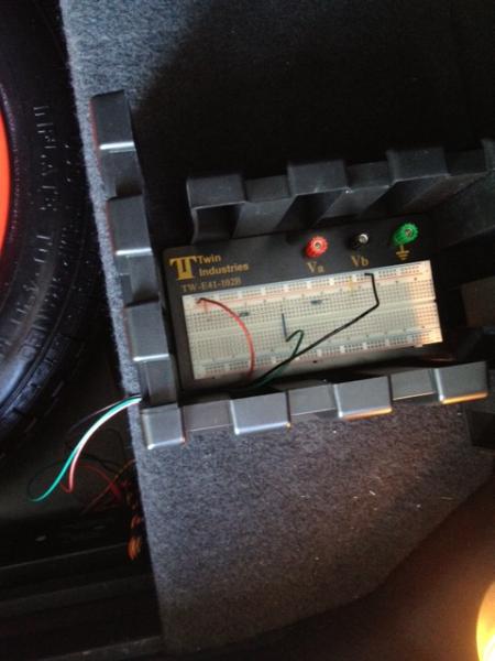
I rebuilt the simple circuit with 75 ohm resistors to reduce the total current. I measured 13 mA in the sensor input from this circuit.
Connect two 75ohm resistors in series between:
+ pin 25, blue
- pin 3, orange-yellow
Tap the center of them and connect to the lateral accelerometer input
pin 20 black-green
I have run this for several days now and the system is permenantly in firm mode with no suspension faults. I am interested in a switch, but if you didn't want to ever turn it off you could make this little circuit up and wire it in near the control box.
If you want a toggle switch, I would put it between the voltage divider and the sensor input.