When you click on links to various merchants on this site and make a purchase, this can result in this site earning a commission. Affiliate programs and affiliations include, but are not limited to, the eBay Partner Network.
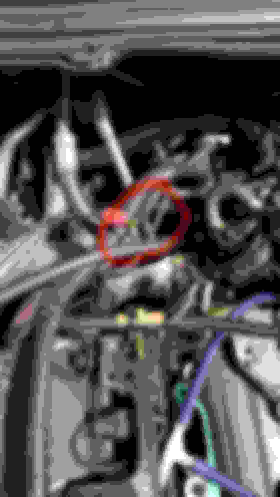
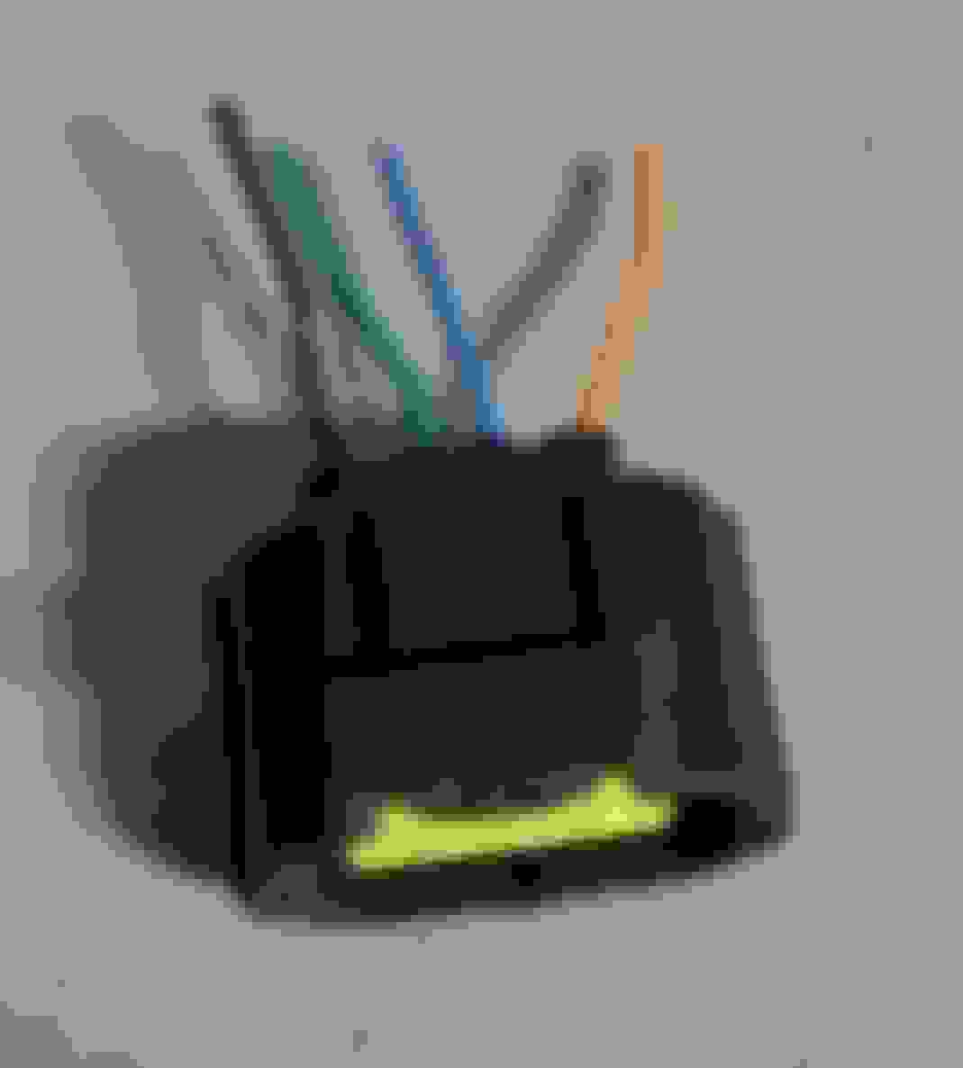
A few years ago, I did some supercharger mods on my 2000 XKR, that did not work out. I am in the process of returning the engine to stock condition. I have a question about an electrical connection in the engine bay. The first picture shows the wiring harness on the passenger side towards the firewall. I circled the particular wring bundle in question that had been spliced to a different connector as part of the modifications. The second picture shows the OEM connector that was cut off. There are four wires: Orange, blue, green, and black.
What I would like to know is: I haven't located the other end of the connector, what does this group of wires and connector go to?
The loose connector is for the throttle position sensor.
I can't make out the colours on the circled area:- it looks like two green and a yellow connecting to three black
Can you separate the wires and also show the connector they route to?
It's definitely not the TPS connection because that is already hooked up and was not messed with. The wires and connector I am asking about come out of the same big group of wires, but is a branch that curves toward the passenger-side fender, whereas the TPS wires branch toward the driver-side fender. The wires I circled are meant route to the connector I pictured, so the wires are black, green, blue, orange. i just need to know what it connects to.
Okay, I figured it out. This connector goes to the throttle body and I believe controls the butterfly valve inside the throttle body. The other one I was referring to in my last post goes to the mechanism that holds the end of the throttle cable I believe must monitor and communicate the position of that mechanism, based on how hard the accelerator pedal is depressed.
So that has been sorted. My apologies to michaelh for the confusion.
Stay tuned (if you care) as I work through this. My next step is to order new gaskets for the fuel injector housings that sit between the intercoolers and the cylinder heads and to see if I can locate a couple of specific bolts for the top of the engine (let me know if you have a stash of extra bolts!)
Glad you got sorted.
The 4-way connector is definitely TPS, but I couldn't match up the three wires you circled anywhere on the engine management diagram from JTIS. Here's a snip from the TB area showing the wiring/colours:
So I have the wiring sorted now and am looking into the vacuum, coolant and fuel lines. I have looked at the JTIS diagrams, as well as the Vacuum Routing Diagram label on the left shock tower and have the following questions:
1. There are 4 connections on the induction elbow that sits below the throttle body and connects to the supercharger. In the back (towards the cowl) is where the EGR valve connects. On the left side there are two connections, I understand the large one is vacuum for the brake servo. It looks like the small one is for a hose that has three branches: to the MAP sensor, a purge valve, and a bypass valve.
a. I see the MAP sensor on the cowl and the bypass valve sits on top of the throttle body on the left side, but where is the "purge valve"?
b. The fourth connection is on the right side and is a flexible hose with a heat shield wrapped around it and funny connector with red tabs on the end. Where does this hose go?
2. There are two coolant connections on the throttle body and I see the small, coolant hardpipe coming up from below, on the right side of the engine.
a. Does the rubber hose from that hardpipe connect to the right or left connector on the throttle body?
b. Does the left-side connection go to the rubber hose that disappears into the right fender area?
c. Does the left-side connection include that short metal tube between the rubber hoses?
3. I see that the fuel return line comes off the left-side fuel rail, so the right-side rail takes the fuel feed. The first connection on the fuel feed line is on the left side of the engine bay, can someone describe or send a picture of the fuel line from there to the fuel rail? I know the pressure regulator is in there somewhere, but I don't know how the fuel line is routed and where the pressure regulator sits.
And here is a picture showing the vacuum connections on the elbow. Doesn't show the lines and hoses but should still be of some help. The part load breather connection on the left hand side is for the black plastic sturdy flex hose with a large ring around its connector
Thank you Higgins, those pictures are a great help!
Yes, I now see the coolant connections to the throttle body and EGR make perfect sense. As for the induction elbow connections, the smaller pipe on the left side for "Fuel Tank Vacuum and Pressure Relief" must be referring to the purge valve, which I still need to locate. The connection on the right side confuses me though. In the picture it says that connection is for the fuel pressure regulator and cruise control vacuum. The diagram on the label on the shock tower indicates the fuel pressure regulator vacuum connection comes from the supercharger outlet elbow. That elbow is the large metal piece that sits on top of the supercharger and has a big "V8" on it. I'll have to look into the cruise control system to see if that connection is still made to the induction elbow.
Thanks again, that information really helps my progress.
My jag is also a Xkr 2000, so your car should be the same as mine. If I remember it correct the thin pipe at the right side of the elbow should connect to the fuel pressure regulator that is located at the rear end of the right hand side cylinder bank head. So the distance between the fuel pressure regulator and the connector on the elbow is very short.
The whole debacle put me in the hole more than $12k, after purchasing the kit from Andre and eventually paying a mechanic to rectify the vacuum leaks and purchasing aftermarket parts and paying a machine shop for some of the modifications. All in all, it was a good lesson about a hobbyist messing with a car as unusual and complex as the XKR. If it had instead been a car with a large community of tuners (like a Mustang, Supra or Civic), I'm sure the project could have been put right, regardless of how far out of whack it had gotten, just because there is a wealth of information, parts and support. The XKR left me floundering, even the the knowledgeable mechanic hit a wall when trying to find anyone who could tap into the ECU to tweak fuel maps or timing profiles. I could go on and on, but that would only cause the heartache to return. Rather than just walking away from it, I've collected myself and am trying to salvage the stock car.
On the positive side, I am finding the stock parts and configuration much easier to work on than the incredibly tight spaces required to accomodate the twin-screw kit and parts. It's not as easy as working on a pre-emissions straight-six, but it is really a massive improvement and keeps me from getting discouraged or triggering PTSD . Also, I located the fuel pressure regulator and fuel hose. Those are now in place. I continue to question where the FPR vacuum hose connects. Higgins, I think you are saying there should be a short hose to span the distance to the right side of the induction elbow. The hose on mine is quite long however, it is long enough to go up to the little pipe on the left corner of the piece that sits on top of the supercharger. What is connected to that pipe on yours?
To summarize, of my questions in post #8, the only ones that remain are to figure out the two vacuum connections on the right side of the induction elbow (brake booster/servo and FPR/cruise control). Also, where is the fuel system purge valve?
Some confusing information here, and hopefully I do not make it worse.
Your purge valve is in the left wheel well, behind the left wheel.
The fuel pressure regulator vacuum line is connected just below the intercooler fill/bleed plug, because this need to see boost pressure and are therefor connected after the supercharger.
Thank you NorXKR, I will look for the Purge valve and its vacuum hose.
Just found this in the JTIS Manual -
"The pressure regulator is a diaphragm-operated valve that regulates fuel-rail pressure at 3,0 bar above the
intake manifold pressure. A pipe connects the throttle induction elbow to the pressure regulator to provide
the vacuum control signal. On supercharged engines, the pressure regulator vacuum feed is taken from the
top of the supercharger outlet duct."
So the piece on top of the supercharger is called the outlet duct and the FPR hose connects to it on the supercharged engine, but to the induction elbow on non-supercharged engines.
So on the supercharged engine, the small port on the right side of the induction elbow must be only for the cruise control and I am still trying to find that hose.
I think I have things just about figured. Going to start full reassembly soon. Hope to have a test firing early December. I'll have to siphon the old gas out of the tank and replace with new. I just hope all the sensors communicate properly with the ECU and allow the engine to run. If not, we are looking at a tow to the dealer, or the Jag repair shop I suppose. Just have little confidence in it running well after all the disassembly and reassembly.
Thanks to those who contributed information during this learning process. I can diagnose and R & R or repair just about every mechanical part on a B5 Volkswagen 1.8L Turbo Passat, but feel like a 10-year old in the bay of the XKR. It's all in my head I know, but I am self-taught and not a true mechanic. I will update when I know more.
You do not have any vacuum connections to the cruise control on your 2000 XKR. It is pure electronic. The older cars have vacuum operated cruise control.