
XK8 Security module wiring


Good day enthusiasts and guru's.
I have a 97 XK8 convertible, that the security module in the boot needs replacing due to water damage. I bought the car with this known problem.
I have bought another module, but there are 3 of the connecting wires that plug into the module via the harness, have pulled out of the harness end clip.
If anybody has any experience with this wiring order, or has pictures of a fully functional harness end clip, I would be most grateful for the help.
I have looked at the wiring diagram, but it is still not very cleat to me which wire goes where.
Short of buying an entirely new harness just for this small fix, any inputs would be much appreciated.
This is preventing me from getting the roof working (I believe the security module also controls this) the valet mode to release (stuck in valet mode) the reverse lights to work, and the boot open message to clear.
Many thanks in advance.
D


Joined: Dec 2011
Posts: 120,439
Likes: 17,018
From: Durham, UK
I've moved your question from General Tech Help to XK8/XKR forum. This is the place to post specific questions about your model.
The photo is the 16-Way BT40 connector to the SLCM?. Here is the pinout from the 1997 Range Electrical Guide:
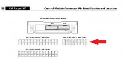
(click on the image to enlarge it)
The main colour / stripe for the pin numbers is:
1. OR = Orange/Red
2. OB = Orange/Black
3. UG = Blue/Green
4. GW = Green/White
5. YW = Yellow/White
6. NK = Brown/Pink
7. OG = Orange/Green
8. S = Slate (Gray)
9. GR = Green/Red
10. Not used
11. UO = Blue/Orange
12. Not used
13. BK = Black/Pink
14. BK = Black/Pink
15. NY = Brown/Yellow
16. U = Blue
Hope this helps.
Graham
The photo is the 16-Way BT40 connector to the SLCM?. Here is the pinout from the 1997 Range Electrical Guide:
(click on the image to enlarge it)
The main colour / stripe for the pin numbers is:
1. OR = Orange/Red
2. OB = Orange/Black
3. UG = Blue/Green
4. GW = Green/White
5. YW = Yellow/White
6. NK = Brown/Pink
7. OG = Orange/Green
8. S = Slate (Gray)
9. GR = Green/Red
10. Not used
11. UO = Blue/Orange
12. Not used
13. BK = Black/Pink
14. BK = Black/Pink
15. NY = Brown/Yellow
16. U = Blue
Hope this helps.
Graham
Last edited by GGG; Sep 28, 2013 at 03:41 AM.
Graham I forgot to ask where you got this info from? It would help me further in trouble shooting if the connections I remake are successful or not. I.E Knowing which wire powers which system, will eliminate redoing them all again as apposed to just the inop system.
Many thanks in advance.
Dion
Many thanks in advance.
Dion
Veteran Member
Joined: Aug 2009
Posts: 1,205
Likes: 434
From: Milwaukee, WI
Graham I forgot to ask where you got this info from? It would help me further in trouble shooting if the connections I remake are successful or not. I.E Knowing which wire powers which system, will eliminate redoing them all again as apposed to just the inop system.
Many thanks in advance.
Dion
Many thanks in advance.
Dion
Jaguar electrical reference
Thanks Paul, much appreciate it! That problem is now solved thanks to you gents, so I am for ever indebted to you.
I ended up cutting the harness end cap off and adding ends individually to each wire and then pressing them on in the right order. Not ideal, but it works!
My next issue now is that the roof will still not operate. I can hear the pump run, and the driver and passenger windows open slightly (like when opening the doors) but it then seems to time out and the windows close again.
It may be the fluid which seems ok, but I have not really checked it properly yet.
Other than that, all the other associated woes are sorted.
My thanks again, and hope I can return the favor some day. :-)
Dion
Hi guys. Just a quick note of thanks.
This is a copy paste of what I posted in another old thread that I had used to troubleshoot my module and roof problems. Your help and assistance got me moving in the right direction, so please see below as my thanks to you again.
This thread really helped me get my roof sorted out as well. I bought a water damaged 97 convertible, with a damaged SLCM (security locking control module) So many thing didn't work. The roof being one. So after buying a second hand module off ebay, I had to modify the connectors due to the original ones being corroded. Got it connected up and it fixed all the small things (stuck in valet mode, no reverse lights, boot open warning) But the roof still did not work. I could hear the pump run, but nothing else happened. It was only after replacing the reverse light fuse that had since gone in all the wire work, that the roof worked perfectly! It was in the fully closed position, 1st press opened and worked as advertised. 2nd press closed and seated perfectly.
I am not sure if this is even related, but that is all I did and the roof worked after that. So if you are still battling with yours, it might be worth checking that 5A fuse in the boot fuse box.
Thanks to all for their posts here over the years, every little bit helped.
Safe roof down travels :-)
Dion
Trending Topics
Joined: Dec 2011
Posts: 120,439
Likes: 17,018
From: Durham, UK
Graham I forgot to ask where you got this info from? It would help me further in trouble shooting if the connections I remake are successful or not. I.E Knowing which wire powers which system, will eliminate redoing them all again as apposed to just the inop system.
Many thanks in advance.
Dion
Many thanks in advance.
Dion
It's part of JTIS ( Jaguar Technical Information System - the Workshop Manuals) which you can download from the forum:
https://www.jaguarforums.com/forum/g...rchives-65926/
With the project you've taken on, JTIS will be a big help.
Graham
Everything all sorted thanks gents. I now have a fully functional 97 XK8 with only 16230 original miles on it to enjoy!
Next posts will be about the body conversion.
My thanks again to all who gave inputs and advise.
Next posts will be about the body conversion.
My thanks again to all who gave inputs and advise.

Thread
Thread Starter
Forum
Replies
Last Post
Currently Active Users Viewing This Thread: 1 (0 members and 1 guests)