When you click on links to various merchants on this site and make a purchase, this can result in this site earning a commission. Affiliate programs and affiliations include, but are not limited to, the eBay Partner Network.
I am having the same problem. I replaced a stepper motor in my cluster for the temp gauge, and after I plugged it all back in the temp gauge now works but the display is dead. I pulled it all back apart and checked the resistor and both capacitors. All checked good. With the display connected to the main board I ohmed out the connections from the main board to the the display and all is good there also. But yet, still no display function at all. Any ideas on were I can check next?
First thing, I’d like to extend a hearty thanks to Christian 96 XJR for documenting this repair. The odometer on my ’02 S-Type recently started to slowly flicker. It progressively became worse over a few months until it was almost entirely dead. I work with electronics, but have no idea how he narrowed down the fault to a cold solder joint at a particular resistor. (In my case, the capacitors were fine and I didn’t touch them.)
If experiencing a similar problem, please do NOT try simply swapping with another instrument cluster, new or used. As I understand it, the instrument cluster is the heart of the security system and requires VIN-specific programming. It’s not plug and play by any means, and may cause LOTS of grief if not done properly. This repair is so simple, I’d see no need to try anything else.
I’m adding some more pictures to help the next guy, especially details of how to remove the wood trim from the face of the dash to allow removal of the instrument cluster. My car is a LHD US model, so if working a RHD vehicle, it will be a mirror image. Other than removing the vents, the entire job was quite simple. The vents gave me some grief, as they are apparently an important structural component, judging by how they were secured. But other than this aspect, don’t let this repair scare you away.
To safely remove the instrument cluster, you’ll need to disconnect the battery. Adjust the steering wheel all the way aft and down for best access. Put the seat wherever you want it, too, since you can’t move it without electrical power. Make sure your key works to unlock the trunk, too, in case it accidentally gets closed. I was planning to close the trunk in case of rain, so as a precaution I also unlocked one of the seatbacks and folded it forward. That way, if everything went wrong and I somehow couldn’t open the trunk from the outside, I could crawl through and pull the emergency release when it was time to reconnect the battery.
Here are some tools required. You’ll need an assortment of picks, small screwdrivers, a Torx T-20 screwdriver, a long thin straight screwdriver, and plastic trim pry bars. Not shown, you’ll also need a #2 Phillips screwdriver, and a 7mm socket with a long extension. To prevent scratching the instrument cluster, you’ll also want an ugly beach towel for use as padding.
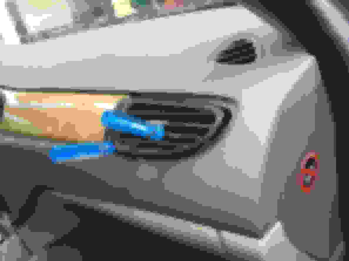
To remove the wood trim, you’ll first need to remove the four vents on the face of the dash. Each is secured by locking tabs, released by reaching through the front. Here’s a view of the vent next to the passenger door, showing the battle with the locking tabs. I’ve only shown two picks in use, but it’s a little fun as there are actually four locks at this location. Once you release the locks, use the plastic trim pry bars to work the assembly free. Don’t pry with screwdrivers as you could leave ugly dents in the dash:
Here’s a view showing two of the four locks, with one retracted and one extended. This is still the vent closest to the passenger door. Note the foam seal where the vent plugs into the ductwork. If the seals are deteriorated, you could replace them with similar foam tape from your local hardware store:
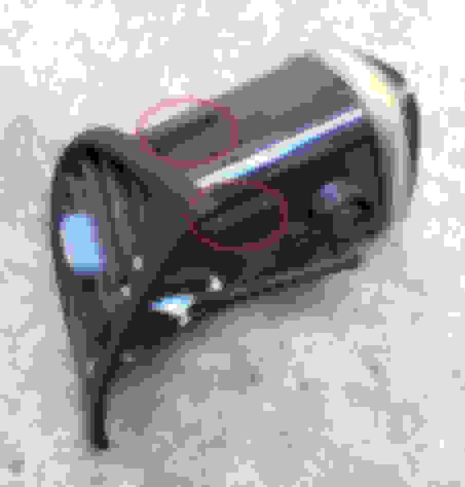
The two center vents and the one at the far right each have four locks. Two are on the top, and two on the bottom. This picture shows a top view of these three vents. The locks are circled in red. The locks on the bottom are not shown but are in the same general location. Peek through the baffles with a strong flashlight and you can see the locks. If you look carefully at the picture, you’ll note some of the locks broke off during removal, but this is no big deal. I’ve no idea why Jaguar opted for so many locks, as just one top and bottom would have been more than adequate. Don’t worry if you lose track of where the vents go, as they are labeled on the top.
The vent by the driver’s door is an oddball. This is the one that really put up a fight for me. Unlike the others, it only has three locks. This view shows the lock on the top and the side:
Here’s the bottom view of the driver’s side vent, showing the single lock underneath:
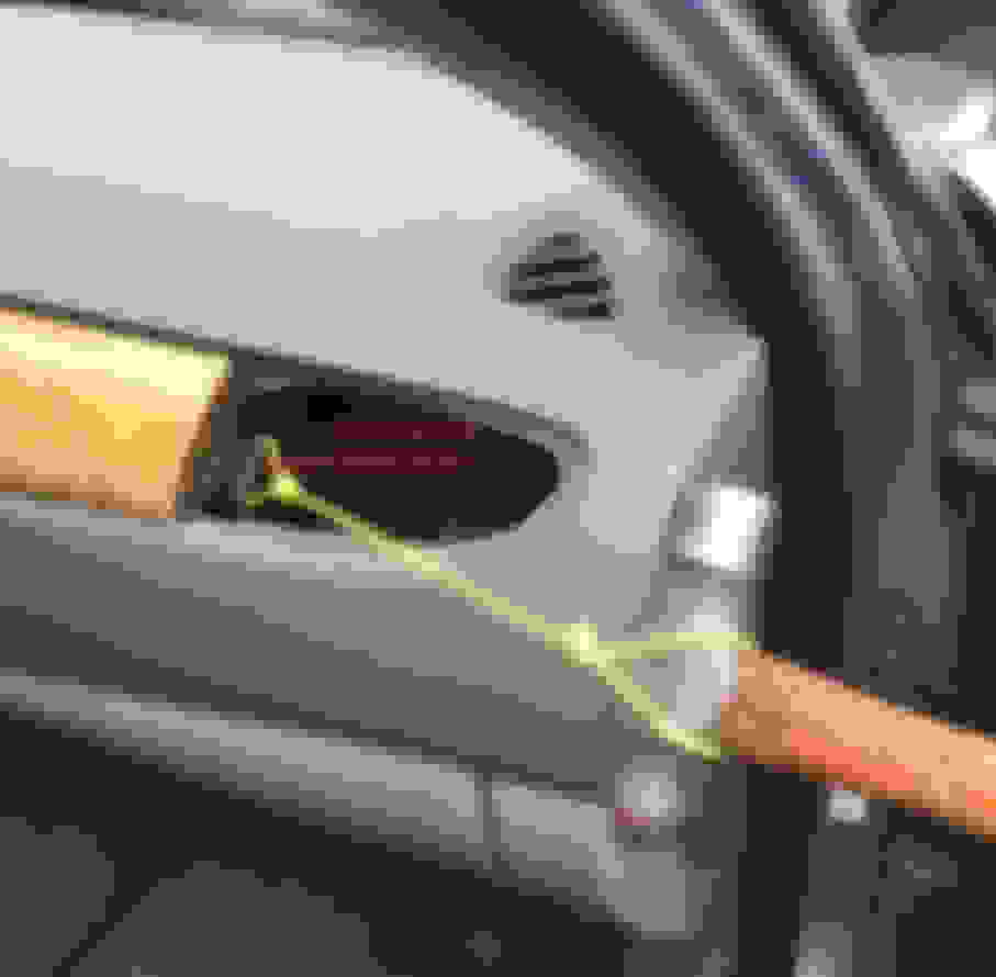
With the four vents removed, it’s time to remove the wood trim plate. Over at the far right, previously hidden by the vent next to the passenger door, you will find a locking tab. Pull this tab to the right to release a keyhole locking plate:
Expect some resistance to getting this piece to budge. You could grab it with a slide hammer with a J hook, but I rigged up something even simpler. Before the woke police issues a warrant for my arrest, that’s just a piece of sturdy string with a loop at each end, not miniature nooses. The hammer provides some weight for motive effort. Put a little slack in the string and gently bump the hammer to the right. This simple arrangement made quick work of sliding the keyhole plate to the unlocked position. Once released, tap it back in about 1/8” in to fully release the hidden fasteners:
Getting a bit ahead of ourselves, here’s a view after the trim plate is removed, to give you an idea what’s behind there. Two protruding studs on the back of the trim plate are secured by the hidden keyhole plate.
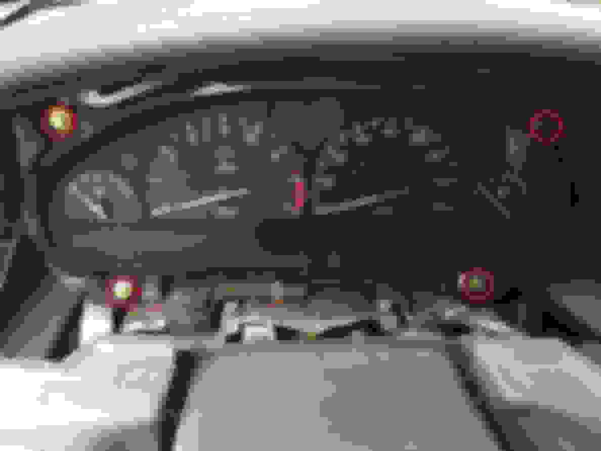
Before the trim plate can be removed, you’ve got five screws and the hazard/trip computer switch to remove. Here are two screws at the far left, circled in red:
In the center of the dash, two more screws along the bottom can be seen, circled in red. The fifth screw is hidden behind the hazard/trip computer switch. To remove this switch, work it loose with your trusty plastic trim prybars. You can also push from behind:
There’s not much slack in the harness to the switch, but it will come out about an inch or so. This picture is a staged shot after the trim panel was removed, and it shows where to reach with a long screwdriver. You can release the lock and pry it apart all in one motion. Access will be tight with the trim panel still installed, but it’s not too difficult. Note the use of the ugly beach towel, with more details later.
With the keyhole plate unlocked, and the five screws removed, the trim panel can now be removed. Here’s a view of the backside, with the five screwholes circled in red:
Here’s a detail of the two hidden fasteners at the passenger side, retained by the keyhole lock plate. There’s no need to adjust them, so don’t touch these fasteners:
Finally, the moment for which we’ve been waiting! Put the ugly beach towel (not shown) in place to prevent damage, and remove the four fasteners (circled in red) with a 7mm socket and long extension:
Tip the top of the cluster aft, and you will see the three electrical connectors that must be released. Access looks tight, but it’s not too bad:
Reach in with your long straight screwdriver, and you can release the lock and pry the connector loose in one motion. The connector at the far right has already been worked partially loose:
Here’s a close-up of the three connectors after the cluster was removed, showing where to release the locks. Don’t worry about labeling them for reinstallation, as the harness will hold them in the correct order:
Place the cluster face down on a padded workbench. Note the use of a second (!) ugly beach towel. This is advanced level stuff. Most guys only have one ugly beach towel. With a Torx T20 screwdriver, remove the four fasteners circled in red and then lift off this rear cover:
Note this placard, warning you not to store the cluster face down. It should be fine to briefly work on it like this, but if you have to leave it for any amount of time, reinstall the rear cover and store the cluster face up.
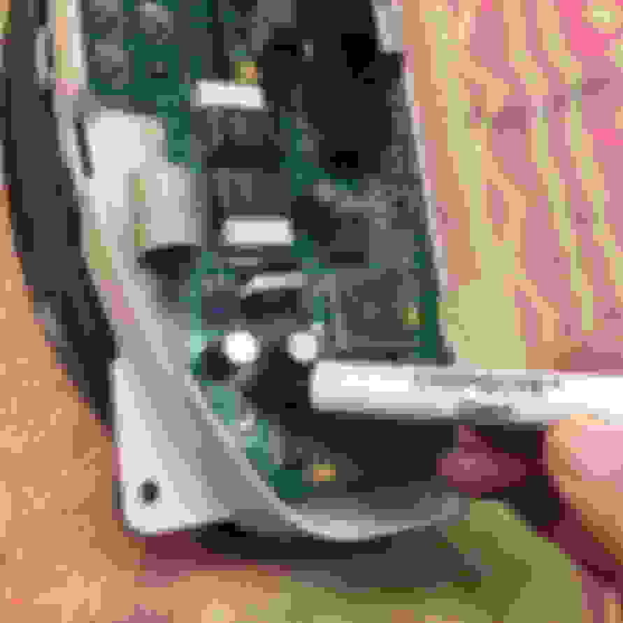
I homed in straight on the suspect resistor. On the circuit board, it’s labeled R1 and is right next to the two big capacitors. Sure enough, the solder joint was dull and cracked. (A proper solder job should have a shiny surface.) I had to use a lighted magnifying glass to see the crack. I applied a bit of liquid flux and just reflowed the existing solder. I reinspected the joint under magnification to be positive of a good repair:
If you’ve never soldered surface mount components, here’s a good primer. The guy has an Australian accent, so he must know what’s he doing:
I inspected the two previously mentioned capacitors, but they looked fine so I didn’t touch them. In case you do find yours in need of replacement, here’s a close-up showing the specifications:
Those are 220 microfarads, with a 50V rating. The Panasonic FC series was recommended as a replacement. The existing capacitors measures 12.5mm diameter and 15mm long, with through pins on one end. (Note these are NOT surface mount like the resistor.) Here’s a Panasonic datasheet:
Please don’t hold me to this, but it would appear Panasonic # EEUFC1H221S would be correct for this application. You could order them from any electronic supplier such as Mouser or Arrow.
With the circuit board repaired, reassembly is the reverse of disassembly. (Don’t you hate seeing that?) The gauge needles are free to float, so hold the right side of the instrument cluster up to make sure the needles are parked to the left before installation. I don’t think it would hurt them if installed sitting at full scale, but why risk it?
The only other thing I’d suggest is to reconnect the battery after installing the instrument cluster, but before reinstalling the trim plate and dash vents. That way, you can test your repair and know it’s good before putting everything else back together. Also, you may need to readjust the steering column during reassembly, so you’ll need electrical power for that.
Watch out for this flexible baffle that fits around the steering column. I needed several tries to get this properly in place. I eventually used my thumbs to hold this baffle flat until I got it to drop down behind the upper shroud on the steering column. If the baffle gets bunched up, the trim plate won’t seat properly.
Courtesy of Paul792, here's another tip I'd like to add to make it easier to remove the vents and trim panel.
When releasing those miserable little plastic locks (not his exact words) inside the vents, push gently on the face of the vent. This helps relieve tension on the locks and makes them easier to release. Same thing when it comes to sliding the keyhole plate that secures the trim plate on the passenger side. Push gently on the face of the trim panel, and this helps relieve tension so the plate is easier to move to the unlocked position.
My trip compter readout works and does not flicker but it is very dim so much so that it is nearly impossible to read during daylight (even in the shade). Yes I have used the dimmer switch and it does vary the brightness. Is this a globe or an LED readout please? Thank you.


 and it does vary the brightness. Is this a globe or an LED readout please? Thank you.

