When you click on links to various merchants on this site and make a purchase, this can result in this site earning a commission. Affiliate programs and affiliations include, but are not limited to, the eBay Partner Network.
2005 XKR Stock Nav to Pi Powered Gauges and Audio Upgrade
Evening all, it's been a while!
Our 2005 XKR has had an Alpine premium audio system with a slightly dodgy amp for many years. The final nail in the coffin was a missing grommet and british winter road salt water getting into the CD changer and killing it, which went un-noticed for some time. (Side note, do any late XK8/R owners have a lot of taped holes rather than grommeted? Ours has lots of tape rather than grommets in places that only could have happened at factory).
Rather than keeping the stock system, I've decided to go down the new head unit, amp and nav route, whilst keeping the stock nav screen. Ideally I would like to swap out for a triple gauge setup but finding a set of matching veneers that also have the passenger airbag light that was on the later models is proving quite diifficult.
I am keen to retain a stock look, so the android touchscreen route was out of the question, although I've seen some pretty neat solutions. I was also impressed by this system was but I confess I do not have the skills to get the gauges via bluetooth OBD working on linux, and I did not want to interface with the stock system. A Raspberry Pi and ancillary DC-DC converters/Video converters will be housed in the now dead CD changer unit. The Pi will be running Android with Torque Pro gauges, and perhaps Headunit Reloaded if I find a nice spot for a rotary encoder knob and want to use Android Auto.
So far I have ordered and partially fitted:
Pioneer SXT-C10PS OEM/Retro style headunit
Incartec single DIN compatible fascia and steering wheel control interface
BLAM Relax RA 251 D Monoblock amplifier
GBS-8100 VGA to RGBS converter
Micro HDMI to VGA Adapter
Raspberry Pi 4, 4GB
Generic BLE 5.0 OBD2 reader
The plan is to try and avoid cutting into the stock harness if I can, so I am doing a dry run with some dupont pin connectors, before ordering the correct AMP (now TE Connectivity) Multilock 070 connectors.
I haven't gone for a DSP amplifier *yet*, as I've got a nice compact 6 channel unit in my soon to be sold camper van. For now, the Pioneer seems to handle the stock speakers okay. I also wanted the amplifier to fit in the existing equipment rack in the back, it is easier to fit a 6 channel DSP amplifier + monoblock stacked within the rack rather than a larger 8 channel. The future DSP amplifier is essential if I ever want to route audio from the Pi as the SXT-C10PS has no rear auxilary input, plus taking SPIDF out direct from the Pi to the DSP would keep the audio very clean.
Using the GBS-8100, I've managed to inject RGB+S video to the original navigation screen, but I've encountered my first hurdle: The stock navigation screen will not power on unless the original headunit is plugged into the yellow 26 pin 185879-1 connector and multilock power. The headunit and nav screeen have 3 wires between them and I've identified that the Pin 8 Orange wire wakes up the nav screen, but it is not a simple ignition feed or a line being pulled to ground. The screen does not seem to care whether its original DVD navigation unit is plugged in either, it seems the stock headunit holds the cards in this case.
Message #58 on this post here alludes to someone being able to keep their screen powered up even without the headunit. Any insight about this from the hive mind would be appreciated!
I also want to try and tie in the factory Motorola microphone, but it seems to need a voltage applied to it/ i'ts not something that can be adapted standard 2 pole jack.
Whilst I scratch my head on these ones, I'll get to replacing the blown bulbs in the AC and hazard/fog/seat controls.
Pictures to follow, just thought I would write up what I completed over the weekend!
Sounds like an interesting project. I ditched the OEM screen for a Garmin sat nav as I felt it was the easiest way to upgrade the screen.
Are you absolutely sure that pin 8 is the essential connection? If it isn't a straightforward switched ground or power, then is it the data line from AI-NET? I think I would go back at this point and double check everything, because I'm not sure why the head unit would be controlling the sat nav.
Couple of other observations:-
Try using a Wifi dongle rather than BLE - the bluetooth stack is bloated and horrible compared to WiFi.
I replaced the factory microphone with a new one and re-used the wiring - it works fine.
From what I've tried so far, if I pull the three wires that go between the head unit and nav screen, the orange pin 8 wire is the only one that tells the screen to wake up. Interestingly the on/off button works when pin 8 is plugged in too. I need to get a scope on it and check out what it's doing.
There is no AI-NET connection between the headunit and nav screen, and the screen doesn't seem to care about the nav DVD unit not being plugged in.
There are two lines that go to the dimmer control module, these seem to be wired directly to the distribution point rather than through the head unit. There are two additional lines that went between the screen and DVD unit, likely to pass on the button presses.
I feel like I'm missing something extremely obvious here.
I agree with your comments on Bluetooth. I went with a BLE dongle since I was worried about power consumption when the car is off. If it's not reliable, I will try and look for a low profile WiFi dongle, assuming they have some sort of auto shutdown to prevent battery drain.
I'll do what you suggest and just reuse the wiring for the microphone. I had a little play at lunch and I can get the guts of the standard new mic into the casing of the old Motorola one.
When I converted mine to the Garmin, I kept the OEM screen surround and buttons and wired the backlights up to that dimmer output, so the buttons all light up and look like the OEM version, controlled by the dimmer knob. Maybe that has some role in the sat nav coming on? Hopefully someone who has done this before will chime in as it does sound like there is something obvious that we are missing.
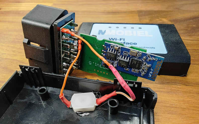
For the OBD dongle you can rewire it to use the switched B+ that Jaguar added as one of the vendor option pins in the OBD connector. Your dongle will come on and off with the ignition:-
That looks like exactly what I need to do to mine.
Regarding the nav screen, turns out it was something obvious I was missing. When I was probing the rear of the head unit, I was doing so with the 26 pin connector disconnected. I probed the back again with some needle probes whilst the 26 pin was plugged in this time.
It turns out pin 14 is some sort of control bus between the nav screen and head unit, so without it being present, the head unit was not outputting 12v on Pin 8.
It appears whatever bus is that is on pin 14 carries some of the controls, at least the ON/OFF button from the nav screen. When the ON/OFF button is pressed, the head unit toggles 12v on pin 8 on and off.
All I need to do is just wire up Pin 8 to a switch that is fed off an ignition feed, then I can turn it off and on when I want. If I wanted to go down the fancy route I could open up the screen and connect the ON/OFF button to a latching relay but that would be overkill for what I want to do.
What a strange way they designed it - maybe it's just to make it harder to use the Alpine sat nav with a non Alpine head unit. The on/off switch is the only button that does anything on my sat nav now, using a cheap latching relay from ebay. On your setup I think I would be tempted to use it as an input signal to your Pi and have the Pi do the switching on and off.
I can now confirm that the pin 14 is the control bus for all the buttons, so I'm guessing the radio puts it on the AI-Net bus and communicates back to the nav unit that way.
Here's the Pi booting into a premade image of Android. I've ended up going with a different android build now, as I wanted the GPIO exposed as I need to have a script that monitors the cars ignition line to safely shutdown the Pi when ignition is off. The Pi shuts down quickly enough that it can be powered by an 10 second timer relay, so sequence of operation is as follows:
Ignition>timer relay engages>Pi powers up>monitor script starts monitoring ignition via GPIO pins>ignition off>script executes shutdown>after 10 seconds relay disengages and standby power to Pi and ancillaries is cut.
I'm not an expert at coding so Claude AI has been a big help in modifying an existing script to support my use case and compiling it on the Pi itself.
I've gone with @dibbit suggestion of getting a Wifi OBD2 dongle instead, so that's in the post. It will stick out a bit too much, but I've got an OBD2 harness left over from a tracker from an ex-lease car, so will find somewhere to stuff the dongle out of sight.
The parts will squeeze into the CD changer, I'll stack the DC converters on top. I may also need to add a filter if alternator whine is an issue, hopefully not. I'll make up a VGA lead from some bare D-Sub connectors as no way an off-the-shelf one will fit. Mounting the connectors will be a bit irritiating due to the housing design that used to accomodate the shock absorbers, but I'm sure I'll find a way. The CD changer sliding door will become a useful access hatch to swap the SD card or access the USBs on the Pi. The EDID emulator was an unexpected addition, but the Pi did not want to output without it as the GBS-8100 does not supply EDID like a monitor would.
I'm also going to run a HDMI and USB cable from the dash to the boot, as this screen matches the dimensions of the stock Sharp unit very closesly, and I have a feeling I'm going to want to swap it out at some point. Only downside is it's glossy, not matt finish. With some modification, it can take an external PWM signal and I can use a �3 DC to PWM board to convert the car's illumination/dimmer line to allow the screen to dim with the controls as the stock one does. You can probably tell I'm questioning my decision to retain the stock screen now!
On the radio side I'm still waiting for my connectors to come from Mouser, but I've at least figured out that I need to also link pin 20 of the yellow 26 way connector to the illumination wire on my new radio in order to get the dimming function to work properly. The incartec harness connects the illumination line to the parallel 12V ignition feed so the radio was staying permanently dimmed when plugged in initially. Note, TE are axing the AMP Multilock series, so soon all we will have are questionable clone connectors.
I wanted to fit the DAB aerial at the very top on the drivers side of the rear screen, so I ended up removing the rear quarter panels in additon to the rear bench seats. The headlining, rear parcel shelf and A pillars are getting re-ulphostered soon, so it looks like I've done half the interior removal for them. I also stripped out the PSE to centre console harness, the long dead PSE and BTUM module, JAGCD-HF BT module and harness, so maybe 1kg weight reduction
I'll steal the PSE harness centre console connector to get the mic hooked up with the stock wiring. The new mic fit in the original housing better than the original, since it didn't have a PCB. Mic quality is adequate from what I've tested so far.
For the subwoofer remote, the potentiometer is going to be mounted in the inside rear of the centre console, next to my FM antenna switch. The remote seems to be the same across all these amplifiers, using an RJ11 connector, very simple to shorten the wire, modify and delete the LED.
Again, more pictures to follow but thought I would give an update.
Work has been crazy for the past month or so and will continue to be for a while, but the weather has been nice recently so I had to at least get the stereo working!
It matches the interior really nicely, unlike some of the modern single DIN units you'll find. The lights are also adjustable so it matches the stock lighting at night perfectly.
Behind the scenes, I have a few adapter harnesses that I made up so I didn't have to touch the stock wiring.
First, we have the 20 way radio connector, this connects to a Perfboard mounted connector where I've linked out various pins which do the following:
- Send the IGN II signal to the back where the Pi will be
- Illumination control (not wired on the incartec harness)
- Steering wheel controls
- Antenna power
- Subwoofer power
- Nav screen power switch
All of the extra functions are using the now spare telephone wires on this connector that run front to back.
Not pictured, a plug to replace the phone harness under the centre console. This:
- Has a pigtail that runs to the microphone port on the radio, uses the factory wiring/location for the new mic in old housing.
- Loops the IGN II Run power that used to be provided to the phone module, back to the radio harness then through to the Pi in the rear.
- Connects to a switch in the centre console that controls the Nav monitor.
Centre Console, left to right:
- Antenna control
- Subwoofer Gain (A nicer knurled pot. knob is in the post)
- Nav Monitor On/Off
Subwoofer amplifer:
I'll have to pull a feed from the battery when this gets swapped for the DSP amplifier, but the stock 30A feed will more than suffice for now. The subwoofer coils are linked in series (pink loop on amp connector) as I wanted to give the amp a 4 ohm load.
Once the summer rolls round and I have a bit more free time, I'll have to finish the Pi powered Nav screen and also mount up all the hardware in the original media rack in the boot. At least for now, I know it'll all work, it just needs buttoning up!
Last edited by Saajan_B; Apr 17, 2026 at 05:08 PM.