
X300 ABS C1095 DTC fault.

Thread Starter
|


Joined: Dec 2009
Posts: 13,758
Likes: 9,713
From: Wise County,TX
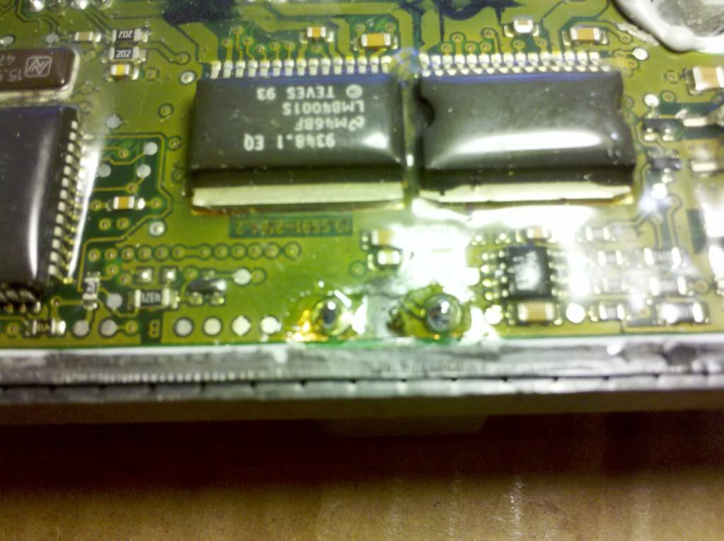
Most of the time the C1095 DTC for the ABS is caused by the same problem the X308 cars have. The pins on the circuit board for the pump motor crack and connection is lost. The ABS module reports faulty pump motor because the circuit is broken. I found an old JLM12004 ABS module in a box while I was cleaning the shop so I decided to cut it open like I do for the X100 and X308.
Found poor/cracked solder on the pump motor pins so I resoldered them.
The circuit board on the X300 module is set lower than the seam so there is less chance of cutting into the board when dissecting the case. The X100/X308 boards are level with the seam and are damaged more easily.
I took a picture in case anyone was curious to see the board.
These modules are also found in the 1995/96 4.0 XJ-S
The JLM12004 is for the 'EXCEPT TRACTION CONTROL" cars.
bob gauff


Joined: Sep 2010
Posts: 2,114
Likes: 976
From: Indianapolis, IN
Resoldering the joints in his picture will probably fix you up. You just have to have the cojones to dissect an expensive module, and the finesse to do it with out damaging the circuit board in the process. I've done dozens of them, x300's, x100's and x308's. As long as the only fault is the C1095, resoldering does the trick. I have even found a wheel speed sensor circuit that had broken in the same way. Fixed the joint and it was good to go.
Joined: Sep 2010
Posts: 2,114
Likes: 976
From: Indianapolis, IN
I had considered that, but I rather like being able to check all the connector pins while I'm at it. I don't like to have to go back and do other solder joints a second time. Not to mention the aggravated owners it prevents.

Pulled the ABS module off yesterday, as I've had the C1095 code since I bought the car. In fact, just less than a year ago, I took it (the car) by Bob's and we plugged the module he repaired (shown above) into my car electrically and hooked up the WDS and it was code-free, thus confirming both his fix of that module and my C1095 being the board not the pump in one fell swoop, or so I was convinced.
Now the problem: After cutting the module open, I find that I have continuity between the points connected by red lines in the following photo:

which is a blow-up from here:
To my feeble mind, this tells me that I need to look further for the problem, no? I have also reviewed XJRGuy's helpful tutorial here:
http://www.mediafire.com/?rmwfpdxc7jgnbnm
I have also checked both ends of each connector pin (board side and connector side) for continuity across the pin (I know! but one can never be too sure) then from tip of the board-side of the pin to the areas as marked. It is the pin for the brown wire that is connected to the foil, and the red wire that is connected to the surface-mount component. Is this conitnuity the way it should be? I could imagine if a solder crack, I may have intermittent contact...but I've never had an intermittent ABS light, it comes on at about 200 yds of travel after startup like clockwork (eh....maybe a poor metaphor in this case...but already had THAT module repaired by ModuleMasters) and stays on until shutdown.
SO...should I have left my meter in the drawer and just smeared some solder on the two pins?
Here's one showing the dissection:

Now the problem: After cutting the module open, I find that I have continuity between the points connected by red lines in the following photo:

which is a blow-up from here:

To my feeble mind, this tells me that I need to look further for the problem, no? I have also reviewed XJRGuy's helpful tutorial here:
http://www.mediafire.com/?rmwfpdxc7jgnbnm
I have also checked both ends of each connector pin (board side and connector side) for continuity across the pin (I know! but one can never be too sure) then from tip of the board-side of the pin to the areas as marked. It is the pin for the brown wire that is connected to the foil, and the red wire that is connected to the surface-mount component. Is this conitnuity the way it should be? I could imagine if a solder crack, I may have intermittent contact...but I've never had an intermittent ABS light, it comes on at about 200 yds of travel after startup like clockwork (eh....maybe a poor metaphor in this case...but already had THAT module repaired by ModuleMasters) and stays on until shutdown.
SO...should I have left my meter in the drawer and just smeared some solder on the two pins?
Here's one showing the dissection:

Last edited by aholbro1; May 4, 2014 at 09:17 AM.

Veteran Member
Joined: Nov 2007
Posts: 4,502
Likes: 1,068
From: atlanta ga
You may very well have a high impedence connection or a connection that changes with the plug plugged in. Remember, current still flows if two pieces of conductor are touching eash other over sufficient area. I would solder the connector joints, put the pieces together eith some duct tape, then try it, If it works, then sealit. Otherwise , look further.
Trending Topics
Joined: Sep 2010
Posts: 2,114
Likes: 976
From: Indianapolis, IN
Cheers,
Suspicious that my existing soldering iron tip was too large(and dirty/corroded) and existing solder too large (dia) and old(>my X300) and didn't have any flux at all....so I swung by the Shack in Decatur on the way home one day this week and picked up $20 in supplies: 15w iron, .032 dia resin-flux silver solder, and a tub of resin flux.
With "Mageyes" fitted to my head atop reading glasses, I fluxed the pins with a toothpick and gingerly set about trying to solder them without melting the board and having them fall out the bottom. When complete, I was still as skeptical as at the time of my previous post above: Having confirmed I already had intact circuits at those pins...I couldn't see that my just-completed work had substantially changed things. Even so, I taped it up, re-installed, fitted busted left-wing on good enough for short/low speed run and headed out for test. Right on cue, ABS light illuminated in front of the neighbor's house two doors down like every morning.
Removed and placed it to my desk so it could mock me for a few days whilst working replacement wing into shape, and yesterday, remembered my oldest son used to tie flies, and "imagined" he had a clip that held a nice magnifying glass over the workspace. Went on a recon of likely storage places since he was away at the time and came up empty but did find a nice flexible-neck desk-lamp. With lots of light directed on it and the same magnification as before, I made another assault. More tape. Re-install. By now had fitted the replacement wing. Youngest son wanted to accompany me on the post-maintenance-check-ride. Confidence meter pegged on "zero"....down the drive, got an amber caution in upper left of panel...some kind of level-indiator..think washer-fluid but will have to look it up...self-extinguished.....on the road...called out to young son, "ABS light in 3, 2, 1....NOW!....clean panel....."NOW!!!"...wha? ...no light? It's late....out to US380, down the highway a mile, U-turn and back home. SUCCESS!
I've had some decent results with the "macro" focus on my 5mp phonecam, but after numerous tries, I just can't get a good, hi-res close-up of this circuit board. Here is the best post-fix pic I could manage:

(Now to pull it back off and re-seal it )
)
With "Mageyes" fitted to my head atop reading glasses, I fluxed the pins with a toothpick and gingerly set about trying to solder them without melting the board and having them fall out the bottom. When complete, I was still as skeptical as at the time of my previous post above: Having confirmed I already had intact circuits at those pins...I couldn't see that my just-completed work had substantially changed things. Even so, I taped it up, re-installed, fitted busted left-wing on good enough for short/low speed run and headed out for test. Right on cue, ABS light illuminated in front of the neighbor's house two doors down like every morning.
Removed and placed it to my desk so it could mock me for a few days whilst working replacement wing into shape, and yesterday, remembered my oldest son used to tie flies, and "imagined" he had a clip that held a nice magnifying glass over the workspace. Went on a recon of likely storage places since he was away at the time and came up empty but did find a nice flexible-neck desk-lamp. With lots of light directed on it and the same magnification as before, I made another assault. More tape. Re-install. By now had fitted the replacement wing. Youngest son wanted to accompany me on the post-maintenance-check-ride. Confidence meter pegged on "zero"....down the drive, got an amber caution in upper left of panel...some kind of level-indiator..think washer-fluid but will have to look it up...self-extinguished.....on the road...called out to young son, "ABS light in 3, 2, 1....NOW!....clean panel....."NOW!!!"...wha? ...no light? It's late....out to US380, down the highway a mile, U-turn and back home. SUCCESS!
I've had some decent results with the "macro" focus on my 5mp phonecam, but after numerous tries, I just can't get a good, hi-res close-up of this circuit board. Here is the best post-fix pic I could manage:
(Now to pull it back off and re-seal it
Last edited by aholbro1; May 4, 2014 at 11:36 AM.


For $3 more, I could've had a switchable 15/30W; wrestled with myself over it awhile, decided to pocket the $3....but then, pretty much EVERYTHING I know about solder is deisplayed in this thread....
Almost called you the other night when I had the "fail" to try to convince you to trade! - but it was pretty late...so after some sleep and thought I decided to give it one more try. That reminds me....now I'm not sure we made a good test on yours last year. Does WDS run some diagnostics to check it, like going down the road? I recall we just plugged it in electrically, and checked for codes on WDS. Normally, I have a clean panel until it runs a few hundred yards and all the BIT's run and the various systems report in before it decides to tell me all is not well. Just curious if WDS has a work-around to check all that sitting still?
So is the code stored in the ABS module itself? I just sealed it with Permatex black hi-temp this afternoon and reinstalled, haven't driven it yet since then...hope it is really fixed. I'll get it down there before too long...I have a t-stat elbow for you and I need to get your speakers. My son told me this afternoon the folks at our church with the black x308 finally got it to you. Glad of that...sounds like it was nowhere near as bad as she thought when she was trying to sell it as a parts-donor-car!!!
So is the code stored in the ABS module itself? I just sealed it with Permatex black hi-temp this afternoon and reinstalled, haven't driven it yet since then...hope it is really fixed. I'll get it down there before too long...I have a t-stat elbow for you and I need to get your speakers. My son told me this afternoon the folks at our church with the black x308 finally got it to you. Glad of that...sounds like it was nowhere near as bad as she thought when she was trying to sell it as a parts-donor-car!!!
Thread Starter
|
Joined: Dec 2009
Posts: 13,758
Likes: 9,713
From: Wise County,TX
Yes the 2000 VDP showed up on a wrecker. I diagnosed the fuel pump inop!!!!!
I guess I will start there and see what else is wrong. The owner stated the coolant was leaking from somewhere.
bob gauff
I guess I will start there and see what else is wrong. The owner stated the coolant was leaking from somewhere.
bob gauff
Joined: Aug 2011
Posts: 619
Likes: 210
From: Wilmington, DE
I have here a nice module that only required repairing the pump circuit. I got a little aggressive and now need a module. I got into one of the capacitors on my final cut. This module is a bit different from the one pictured above but now I'm on the prowl for a replacement.
Junior Member
Joined: May 2014
Posts: 1
Likes: 1
From: Christchurch, New Zealand
Thanks for this thread!
My X300 had a non functional ABS since the day I bought it. The previous owners (or whoever) fix was to just remove the ABS-bulb from the instrument cluster.
Getting really frustrated with the issue, I was checking ebay.co.uk for a suitable spare part, but thought before replacing the entire ABS module, I might just as well give it a go and try to resolder the module. And guess what, it worked just fine, ABS light stays off and the system is fully functional!
All that just cost me $20 for a soldering iron, I'm happy again
Many thanks,
Flo
