
Rebuilding powerfold mirrors

Thread Starter
|
Senior Member


Joined: Mar 2012
Posts: 100
Likes: 85
From: France
If your powerfold mirror mechanism breaks, you used to have 2 options:
So I decided to go a third path and rebuild my powerfold mechanism myself. It is not cheap but still much cheaper than buying a new one. Futhermore, I discovered and cured the weak point of the design, I now have a powerfold mechanism which I believe will last for life.
First of all the disassembly of the pivot. I will focus only on the difficulties:

You can see 2 diodes that very well could be burnt. If that is the case they need to be replaced by rectifier diode able to withstand 1A. I have been able to measure peak currents close to 1A when the mirror reaches final position.
For those who want to understand this twin microswitch, first you need to understand that the power fold electical motor is controlled by the car body processor with just 2 wires. The car body processor applies 12V in the 2 wires for a duration longer than the time required for the mirror to reach position. In order the prevent burning the electrical motor or breaking gears, the twin microswitch shown below opens the circuit and closes another circuit in order to be ready for the inverse movement when the body processor will apply 12V with opposite polarity. It is key yo understand that the 2 pieces of the microswitch shown below stay still during all the time while the mirror is moving. The 2 pieces of the microswitch only slide, one with respect to the other, when the mirror stops at its final position.

A complete unfold/fold Cycle is depicted below (sorry there is a bit of french left, so you know where I am coming from ;-))

Now the last point consists in disassembling the gear set and the 3 frictions. This is done by uncrimping the black plastic gearset cover on top of the pivot (part #18 below) and removing a big stop washer (part 1 below, be carreful it is under load of 2 big springs and there are a lot of shims and friction rings ready to fly around). Once done you are in front of this:

With such damaged gears, at best the mirror only moves to position but is not able to operate the microswitch (noisy cracking gears at the end of the movement), or even worse, it is not able to move the mirror at all (gear noise all the time). This is only going to deteriorate rapidly.
I decided to have a ring gear rebuilt in stainless steel.
Here is the manufacturing process involving electro-erosion:

- Step 1, build the outline with a lathe
- Step 2, build a copper electrode having the required gear shape with wire-cut method
- Step 3, press the electrode in the stainless still ring (electro erosion)
- Step 4, Cut the spurs with wire_cut method


Here is a rebuilt powerfold pivot with the stainless still ring gear, new diodes and silicon greased frictions:
I can have stainless steel gears built on request and could consider rebuilding pivots if this job is too scary for you.
Cheers,
Bruno
- Buy a new powerfold frame for around �370
- Buy a used powerfold frame anywhere from 50 to �100+
So I decided to go a third path and rebuild my powerfold mechanism myself. It is not cheap but still much cheaper than buying a new one. Futhermore, I discovered and cured the weak point of the design, I now have a powerfold mechanism which I believe will last for life.
First of all the disassembly of the pivot. I will focus only on the difficulties:
- separate the 12 wires from the connector. Here is how I do it. While I am pushing on the needle towards the right with my index, I pull the corresponding wire at the back of the connector.
- Here is the wiring for reassembly:

- Then you need to tear down the 12 wire harness by removing one by one all the wires from the sheath. This is made difficult by the fact that the wires are glued inside the sheath with some silicon to prevent water ingress. So you first need to extract the silicon with a srew driver without damaging the wires or the sheath. Note that you could also cut the sheath and replace it with a new one, but I have been able to save them every time.
- Next is time to extract all the wires from the sleeve (part #15 below) that goes across the pivot.
- Now you need to remove the L shape plastic covering the electrical engine and primary gear set. That gives you access to the 2 electrical engine contacts that need to be unsoldered.
- Turning the pivot upside down, you can now remove the last 2 wires coming from the electrical engine and you are ready to remove the stop washer from the end of the sleeve.
- It is now time to remove the microswitch:
You can see 2 diodes that very well could be burnt. If that is the case they need to be replaced by rectifier diode able to withstand 1A. I have been able to measure peak currents close to 1A when the mirror reaches final position.
For those who want to understand this twin microswitch, first you need to understand that the power fold electical motor is controlled by the car body processor with just 2 wires. The car body processor applies 12V in the 2 wires for a duration longer than the time required for the mirror to reach position. In order the prevent burning the electrical motor or breaking gears, the twin microswitch shown below opens the circuit and closes another circuit in order to be ready for the inverse movement when the body processor will apply 12V with opposite polarity. It is key yo understand that the 2 pieces of the microswitch shown below stay still during all the time while the mirror is moving. The 2 pieces of the microswitch only slide, one with respect to the other, when the mirror stops at its final position.
A complete unfold/fold Cycle is depicted below (sorry there is a bit of french left, so you know where I am coming from ;-))
Now the last point consists in disassembling the gear set and the 3 frictions. This is done by uncrimping the black plastic gearset cover on top of the pivot (part #18 below) and removing a big stop washer (part 1 below, be carreful it is under load of 2 big springs and there are a lot of shims and friction rings ready to fly around). Once done you are in front of this:
-
- 1 stop washer
- 2 friction ring
- 3 thin spring, large diameter
- 4 thick spring, small diameter
- 5 Ring with stops for fully open mirror
- 6 mobile part of the pivot
- 7 friction ring white
- 8 friction ring black
- 9 fixed part of the pivot
- 10 friction ring white
- 11 friction ring black
- 12 frcition ring white (internal splines)
- 13 friction ring black
- 14 shaft
- 15 sleeve
- 16 engine cover
- 17 engine and 1st level gear set
- 18 fixed ring gear
- 19 planet gear carrier
- 20 sun gear
- 21 mobile ring gear
- 22 fixed ring of the microswitch
- 23 moving ring of the microswitch
- 24 stop washer
- 25 protection sleeve
- There are 3 frictions with different sliding torque threshold that are in this order, from the weakest, to the strongest friction
- for moderate torque (during electrically operated mirror movement), only parts #6 to #9 are sliding

- For sligly stronger torque (required to operate the microswitch at the end of the movement, or mirror folded by hand) parts #9 to #14 are sliding.

- Eventually, for a even stronger torque (mirror opening past the normal position towards the front of the car, due to shock or microswitch not working) parts #5 and #9 are sliding.

- It is important that all the 3 frictions slides according their specified torque threshold so they should be disassembled, cleaned, and greased with silicon grease (plastic parts).
- Last but not least, part 21 (mobile ring gear) is almost always damaged and is clearly the weakest point of the gear set. The central part of piece 21 is made of aluminium (the 2 spurs would break if made of plastic due to strong torque to be transmited to the shaft). But the external ring is made of plastic, look at how badly the gears can be damaged:
With such damaged gears, at best the mirror only moves to position but is not able to operate the microswitch (noisy cracking gears at the end of the movement), or even worse, it is not able to move the mirror at all (gear noise all the time). This is only going to deteriorate rapidly.
I decided to have a ring gear rebuilt in stainless steel.
Here is the manufacturing process involving electro-erosion:
- Step 1, build the outline with a lathe
- Step 2, build a copper electrode having the required gear shape with wire-cut method
- Step 3, press the electrode in the stainless still ring (electro erosion)
- Step 4, Cut the spurs with wire_cut method
Here is a rebuilt powerfold pivot with the stainless still ring gear, new diodes and silicon greased frictions:
I can have stainless steel gears built on request and could consider rebuilding pivots if this job is too scary for you.
Cheers,
Bruno
Last edited by bballarin; Mar 21, 2013 at 11:08 AM.

Veteran Member


Joined: Oct 2008
Posts: 4,880
Likes: 1,431
From: Sunny Southport UK
Bruno, superb work and write-up.
The powerfold is a box of tricks isn't it. The wrong or failed micro relays (lh healboard) will break the mechanical stops marked did you find yours in tact?
I have to ask, what is the price of the stainless items?
The powerfold is a box of tricks isn't it. The wrong or failed micro relays (lh healboard) will break the mechanical stops marked did you find yours in tact?
I have to ask, what is the price of the stainless items?
Thread Starter
|
Senior Member
Joined: Mar 2012
Posts: 100
Likes: 85
From: France
Hi Sean,
The stainless steel ring gear is �100 for the first (including shipping to France) �80 for the second. I paid them more than that but now that the guy has the electrode built, he can reuse it many times and that is the reduced rate he told me he would apply now on.
You may want to order directly to him. If you are interested I PM his email to you. He can be paid with paypal.
And with respect to the LH heelboard relays, both were present when I bought the car, just the fuse was burnt in the RH heelboard. I do not think a wrong of failed microrelay will damage the power fold mechanism if this is what you mean. But operating a powerfold mirror that does not work perfectly will most likely accelerate its deterioration.
Cheers,
Bruno

Junior Member
Joined: Jul 2013
Posts: 1
Likes: 0
From: wiltshire
Hi
I have been looking into this problem for several months now, so many thanks for the great post.
Is it possible to get the contact details for the manufacturer of the replacement stainless steel gear?
I have been looking into this problem for several months now, so many thanks for the great post.
Is it possible to get the contact details for the manufacturer of the replacement stainless steel gear?
Trending Topics
Thread Starter
|
Senior Member
Joined: Mar 2012
Posts: 100
Likes: 85
From: France
MP sent to you topcatnew.
A few more details on the rebuilt:
- I replaced the rectifier diodes on the back of part #22 (one was in short circuit) with this reference: MBR140SFT1G 40V 1A Schottky Rectifier Diode SOD-123FL (measured peak current around 0.7A when mirror reach end position)(2 per mirror needed).
- I replaced the protection diodes on the electrical motor with this reference BZX55 type 500mW (0.5W) Zener Diode with a zener voltage of 20V (I made a guess for the 20V, needs to be higher than the highest voltage the car 12V may ever reach into normal conditions)(note: unlike the rectifier diodes, these ones are not mandatory for operation but they protect the car electronics from spikes that might be generated by the electrical motor, specially when it is stopped)(these diode were physically split in 2 parts on my original mirrors)(2 needed per mirror).
One last note, on right side mirror, wires #1 and #7 are inverted on the 12 points connectors ( the rotation direction must be inverted on the right side versus the left side to get the symetrical movement).
Needless to stay, the mirrors have been operating perfectly since then.
Last edited by bballarin; Jul 29, 2013 at 06:56 AM.

Senior Member
Joined: Jun 2014
Posts: 113
Likes: 62
From: Japan
bballarin has kindly offered to contact the manufacturer to make these gears and I have decided to buy them.
So far, I am getting 5 gears (NOT 5 sets)
if anyone else do want them, please let me know so maybe we can get them cheaper overall.
Price to order them originally was 100EUR for one, 80Euro for second.
I am not sure how much lower the price will be for order of more than xx amount.
Rui
So far, I am getting 5 gears (NOT 5 sets)
if anyone else do want them, please let me know so maybe we can get them cheaper overall.
Price to order them originally was 100EUR for one, 80Euro for second.
I am not sure how much lower the price will be for order of more than xx amount.
Rui
Junior Member
Joined: Sep 2014
Posts: 10
Likes: 3
From: Nottingham
Fantastic write up, I kind of understand how it works (I think) not that I could even attempt to build it! Genius level stuff. You should be working for Jaguar on a high consultancy wage with this knowledge.
Anyway to the point.
One of my powerfold mirrors on my 1995 X300 doesnt work. How would I start to diagnose this? It doesnt make any sound or attempt to move at all so I assume its an electrical issue.
Obviously it cant be the switch and its unlikely to be a fuse as I assume its the same fuse for both sides?
Thankyou to who ever can help!
Chris
Thread Starter
|
Senior Member
Joined: Mar 2012
Posts: 100
Likes: 85
From: France
Hi Chris,
I am glad you like the post. My answer is for X308 but should not be much different on X300. There is only one 10 A Fuse and 2 micro relays (one for opening and one for closing). There are all below the rear right seat behind heelboard, the fuse is position 4. Microrelays look like this (cluster of 4, only 2 of them for power fold):
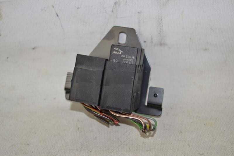
You are right if one powerfold mirror is working it is likely not the fuse nor the relays. So unless there is a deffective wiring in the car, the issue is likely in the mirror itself. If you can remove the door panel, testing pins 1 and 7 for + or - 12V while the other mirror is folding will definitely tell that the issue is in the mirror (maybe the rectifier diodes, see above posts).
I am glad you like the post. My answer is for X308 but should not be much different on X300. There is only one 10 A Fuse and 2 micro relays (one for opening and one for closing). There are all below the rear right seat behind heelboard, the fuse is position 4. Microrelays look like this (cluster of 4, only 2 of them for power fold):
You are right if one powerfold mirror is working it is likely not the fuse nor the relays. So unless there is a deffective wiring in the car, the issue is likely in the mirror itself. If you can remove the door panel, testing pins 1 and 7 for + or - 12V while the other mirror is folding will definitely tell that the issue is in the mirror (maybe the rectifier diodes, see above posts).
Junior Member
Joined: Sep 2014
Posts: 10
Likes: 3
From: Nottingham
Right. Thats on the list of things to try to fix. The Diodes look fairly well buried within the mechinism. Are the mirrors difficult to get off and do you need to remove all the wiring sheath to get to the diodes? I think the diodes seem like a possible weak point. Especially if they have 1A going through them.
Guess it could also be a bad earth.
Guess it could also be a bad earth.
Thread Starter
|
Senior Member
Joined: Mar 2012
Posts: 100
Likes: 85
From: France
Hi Chris,
I do not know from your post if you have tested the presence of + or - 12V between pin 1 and 7 on the connector (car side) while the other mirror is folding. This is the first thing to do. If there is an earth issue, it would affect only one of the mirrors since you say the other mirror is working. There can't be earth contact issue on the mirror itself, both (alternatively + or minus) signals are travelling only on wires inside the mirror (but there could be cut or short-circuit wires, or deffective connector contacts, or dead motor)
For the diodes you do need to remove all the wiring sheath to get to them. But you should be able to test continuity from the connector to the motor contacts without removing the wiring (in one direction only due to the diode) before assessing that the diodes, the microswitch or the wiring is dead.
Have you been able to see the broken power fold mirror working in the past? If yes how did it stop working? Suddenly and completely?
Last edited by bballarin; Sep 17, 2014 at 12:21 PM.
Junior Member
Joined: Sep 2014
Posts: 10
Likes: 3
From: Nottingham
Unfortunatly its never worked in the four or so years I've owned it. The drivers has always worked. It makes no sound or attempt to move at all. However it does operate the tilt mirror/heated mirrors correctly if that sheds any light?
This connector (which is shown in your post at the start). This inside the door? Which I guess involves removing the door card?
This connector (which is shown in your post at the start). This inside the door? Which I guess involves removing the door card?
Thread Starter
|
Senior Member
Joined: Mar 2012
Posts: 100
Likes: 85
From: France
The powerfold circuit (contact 1 and 7) is completely independent from any other function inside the mirror. So the fact that the rest is working does not tell anything about where the powerfold issue is.
If you have never seen it working, I am just wondering if your mirror frame would have been replaced at some point in time by a cheaper non power fold frame.
The connector shown at the beginning of the post is behind the black plastic triangle on the inside of the door, at the bottom front corner of the window. This is also where is the only Torx screw that attaches the mirror to the door. The littlle plastic triangle needs to be pulled gently toward the back of the car (parallel to the glass), not toward the inside of the car, otherwise you will break the tiny tabs on the back. This is made more difficult by the fact that this plastic trim is glued. Use a blade to cut the glue before pulling.
Yes the door card needs to be (at least partly according factory manual) removed. I find it more easy to just remove it completely.