
Understanding the Turn signal wiring diagram


Thread Starter
|
Senior Member


Joined: Sep 2017
Posts: 694
Likes: 279
From: Lincoln Ontario
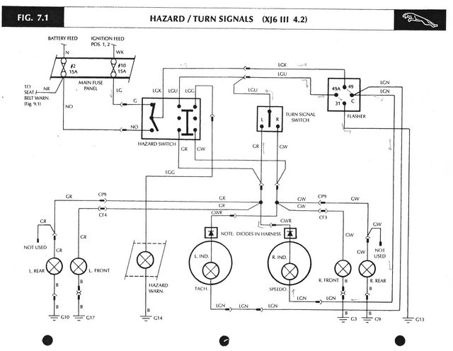
Looking at Fig. 7.1 in the S57 wiring diagrams, can someone tell me why I cannot interpret this. Normally I'm pretty good with wiring diagrams, but this one has me licked!
The following is my (limited) understanding of it:
Assuming hazard is set to "off" in the diagram.
Power leaves the Haz. Sw. at LGK and connects at term. 49 of the flasher.
After that I'm completely lost! Help.
The following is my (limited) understanding of it:
Assuming hazard is set to "off" in the diagram.
Power leaves the Haz. Sw. at LGK and connects at term. 49 of the flasher.
After that I'm completely lost! Help.

Veteran Member


Joined: Mar 2008
Posts: 25,529
Likes: 11,724
From: Pacific Northwest USA
Heh heh. You're not alone. My understanding of it is fleeting and tenuous...sorta like a math concept that you're on the cusp of grasping but can't quite reach the "Ahhhh...HA" moment
This might help
Signals, turn and hazard
Cheers
DD
This might help
Signals, turn and hazard
Cheers
DD
Veteran Member
Joined: Mar 2008
Posts: 25,529
Likes: 11,724
From: Pacific Northwest USA
Cheers
DD
Veteran Member

Joined: Mar 2007
Posts: 9,137
Likes: 2,659
From: Florida
Trending Topics
Veteran Member
Joined: Mar 2008
Posts: 25,529
Likes: 11,724
From: Pacific Northwest USA
I'll find it!
Cheers
DD
Veteran Member
Joined: Mar 2008
Posts: 25,529
Likes: 11,724
From: Pacific Northwest USA
Yeah, that rings a vague bell.
It caused a lot of problems when people went to replace the hazard switch
Cheers
DD
It caused a lot of problems when people went to replace the hazard switch
Cheers
DD
Veteran Member
Joined: Mar 2008
Posts: 25,529
Likes: 11,724
From: Pacific Northwest USA
Veteran Member
Joined: Mar 2007
Posts: 9,137
Likes: 2,659
From: Florida
no worry, just that I wanted to add the following:
I have a Ford door Lock / Unlock solenoid per the pictures below. Very similar to the XJ solenoid, and it only has 2 contacts. (Ground and Hot I assume).
So how can the Ford solenoid do it with two contacts??
I have a Ford door Lock / Unlock solenoid per the pictures below. Very similar to the XJ solenoid, and it only has 2 contacts. (Ground and Hot I assume).
So how can the Ford solenoid do it with two contacts??
Thread Starter
|
Senior Member
Joined: Sep 2017
Posts: 694
Likes: 279
From: Lincoln Ontario
Perhaps it's spring loaded to the "locked"position (relaxed state). Then the single hot contact could be used to "unlock" only.
Or, the unit is chassis grounded and one hot contact locks and the other hot one unlocks?
Just my 2 Canadian cents. I was not even aware that my S3 had a boot lock solenoid!
Or, the unit is chassis grounded and one hot contact locks and the other hot one unlocks?
Just my 2 Canadian cents. I was not even aware that my S3 had a boot lock solenoid!
Veteran Member
Joined: Mar 2008
Posts: 25,529
Likes: 11,724
From: Pacific Northwest USA
Both plausible.
Or, an upstream control module reverses polarity on the two terminals to reverse direction
Just my 2 Canadian cents. I was not even aware that my S3 had a boot lock solenoid!
It's 'lock only' unless modified.
There were 3 variations of electric locking on the Series III....but we're getting way off-topic!
Cheers
DD
Veteran Member
Joined: Mar 2007
Posts: 9,137
Likes: 2,659
From: Florida
Perhaps it's spring loaded to the "locked"position (relaxed state). Then the single hot contact could be used to "unlock" only.
Or, the unit is chassis grounded and one hot contact locks and the other hot one unlocks? Just my 2 Canadian cents. I was not even aware that my S3 had a boot lock solenoid!
Or, the unit is chassis grounded and one hot contact locks and the other hot one unlocks? Just my 2 Canadian cents. I was not even aware that my S3 had a boot lock solenoid!
But yes, this is off topic, sorry.
Below is the Topic resolution hopefully.
Veteran Member
Joined: Mar 2007
Posts: 9,137
Likes: 2,659
From: Florida
Follow the 1 thru 4 diagrams and you will see the error from Number 1 (original published diagram), and Number 4 (showing the difference). This was from the 1990s at Jag Lovers.
The last Text file is an explanation of the diagrams written by the Jag Lovers member.
The last Text file is an explanation of the diagrams written by the Jag Lovers member.

Veteran Member
Joined: Mar 2007
Posts: 9,137
Likes: 2,659
From: Florida
I think the whole problem is at the Hazard Switch wiring. If you can use the Turn signals with ignition switch OFF, the battery power wire is in the wrong connector. It should only power the Hazard Switch from the battery, ignition switch OFF.

Thread
Thread Starter
Forum
Replies
Last Post
JessN16
XJ6 & XJ12 Series I, II & III
4
Nov 25, 2017 12:30 PM
beady
XJ XJ8 / XJR ( X308 )
6
Aug 27, 2015 06:38 PM
satlee
XF and XFR ( X250 )
1
Jan 9, 2014 06:16 AM
Currently Active Users Viewing This Thread: 1 (0 members and 1 guests)