When you click on links to various merchants on this site and make a purchase, this can result in this site earning a commission. Affiliate programs and affiliations include, but are not limited to, the eBay Partner Network.
Injector, injector rail, and injector loom project
Some time ago I started this thread https://www.jaguarforums.com/forum/x...wanted-281293/
which set out how, using a cheap pulser from Amazon and a can or two of carb cleaner, I managed to build a good injector spray tester and injector cleaner. Amazingly all 12 of my long-unused second hand injectors worked perfectly.
The overall plan is to have i) refurbished injectors on a ii) cleaned up rail with iii) a new silicone injector loom; all built up off car, ready to fit as a unit. As I am lucky enough to have a spare engine, I removed the rail from it and that is the basis of the project. In that way I can continue using the car until the time the replacment rail and loom is ready, and just swap them over in a morning when the time comes.
My current loom is a replacement from the original; but is over 20 years old. It is not cracking or failing (as it is fixed to the rail not the bottom of the V) but the connectors to the injectors are starting to look cooked, and are very hard to remove to clean the contacts. The current injectors were also refurbed professionally over 20 years ago, and although the front one I tested is spraying perfectly, they must be due for new seals and filter baskets. Hence the idea to get an entire new rail, loom and injector unit together.
The rail:
I removed the rail by cutting the flexibles leaving the spare engine with the injectors still fixed to it. Then using a gas torch I burned off the old stubs of the flexibles from the rail spigots.
A bath of 75% phosphoric acid cleaned off the surface rust. A quick go in Madame's dishwasher to degrease it and then a spray of galvanising silver paint produced this:
The injectors:
The link above shows how they were spray tested/cleaned. The spray they should produce is shown in the attachment to this post: essentialy a dropless fog. I had in stock a Mr Injector rebuild kit which has everything needed to refurbish them following their cleaning and spray testing. The Mr Injector website is opaque and injector refurb kits are hard to find on it, but this is the kit needed to refurb the injectors on V12 5.3 HE engines. https://www.mrinjectoruk.co.uk/produ...ervice-kit-180
They send instructions with the kit and it is straightfoward to do it.
Fitting the injectors to the rail:
This morning No. 2 son and I fitted the refurbed and cleaned injectors to the rail. We used 8 of the 12 I refurbished and 4 factory refurbished ones from RockAuto that I had in stock. Some notes on the flexible hoses that join the rail to the injectors:
the standard length of the flexibles is 50mm, except for the longer two that are for the front injector on A and B bank. These are about twice as long.
the length of the spigots on the fuel rail is 17mm and on the injectors 16mm = total spigot length 33mm.
Therefore between the spigots the hose length is 50 - 33 = 17mm.
We cut the hose length by 12mm in order to reduce the length of the injector hose between the spigots, but leave a 5mm space to avoid vibration.
The pupose of this is to aid hot-starting after a hot stop, by reducing the volume below the rail that can contain vapourized rather than liquid fuel. This is a Grant Francis mod (turn and bow to the Southern Cross at the mention of his name) and works in the heat of Australia. Before and after photo here: Yellow line hose standard length of 50mm. Blue line reduced hose length by 12mm to 38mm.
NOTE: the hoses are hard to push over the barbs, we used red brake grease to lunricate the barbs which made it far easier. This type of grease gos not attack rubber
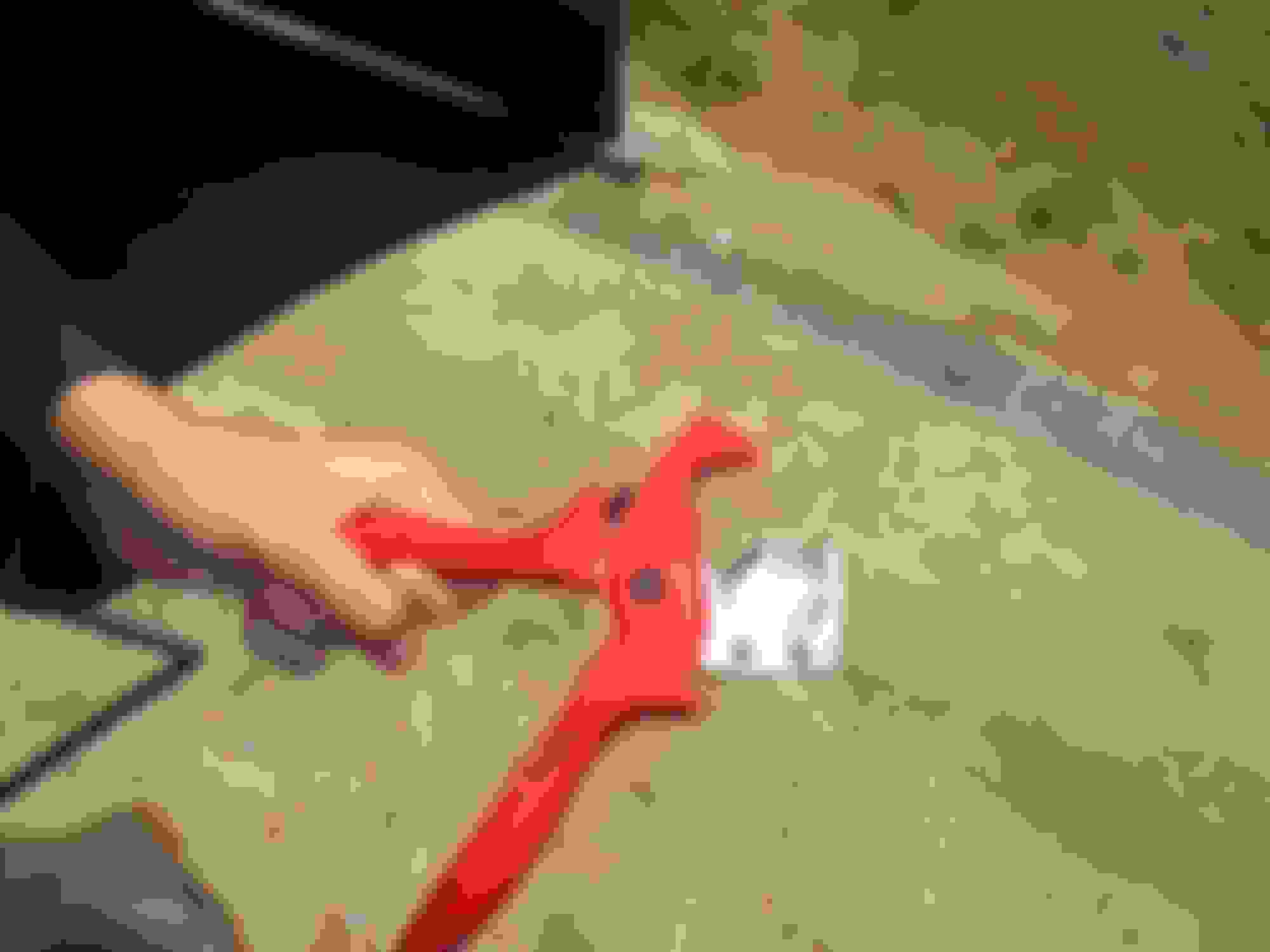
The two long-hosed injectors for the front injector on each bank were also reduced in length by 12mm. The hoses were cut using this superb hole cutting tool which makes a perfect cut: Knipex hose cutting too from Amazon, indespensable if shortening the hoses: https://www.amazon.fr/PlastiCut-coup...85&sr=8-1&th=1
Fuel clips on the hoses, yes or no?
From the Jaguar Factory the hoses had no fuel clips on them to hold them to the spigots, just ferrules at each end (for cosmetic appearance as far as I can tell). Providing the spigot barbs are in factory new condition they do not need hose clips. However they can get scratched when removing the old hoses and can lose their sharp edges. Taking advice from Grant, I decided to fix the hoses as follows:
lightly sand the spigot edges by wrapping a bit of 400 grit paper round the spigot and turning it with medium pressure between finger and thumb. Just enough to make about a 0.5mm flat to the edge of the barb when viewed from the side. The injector spigots had softer steel than the rail spigots, which required more effort. The idea is to ensure that the sharp edge of the spigot barb will not cut into the hose when a clip is used.
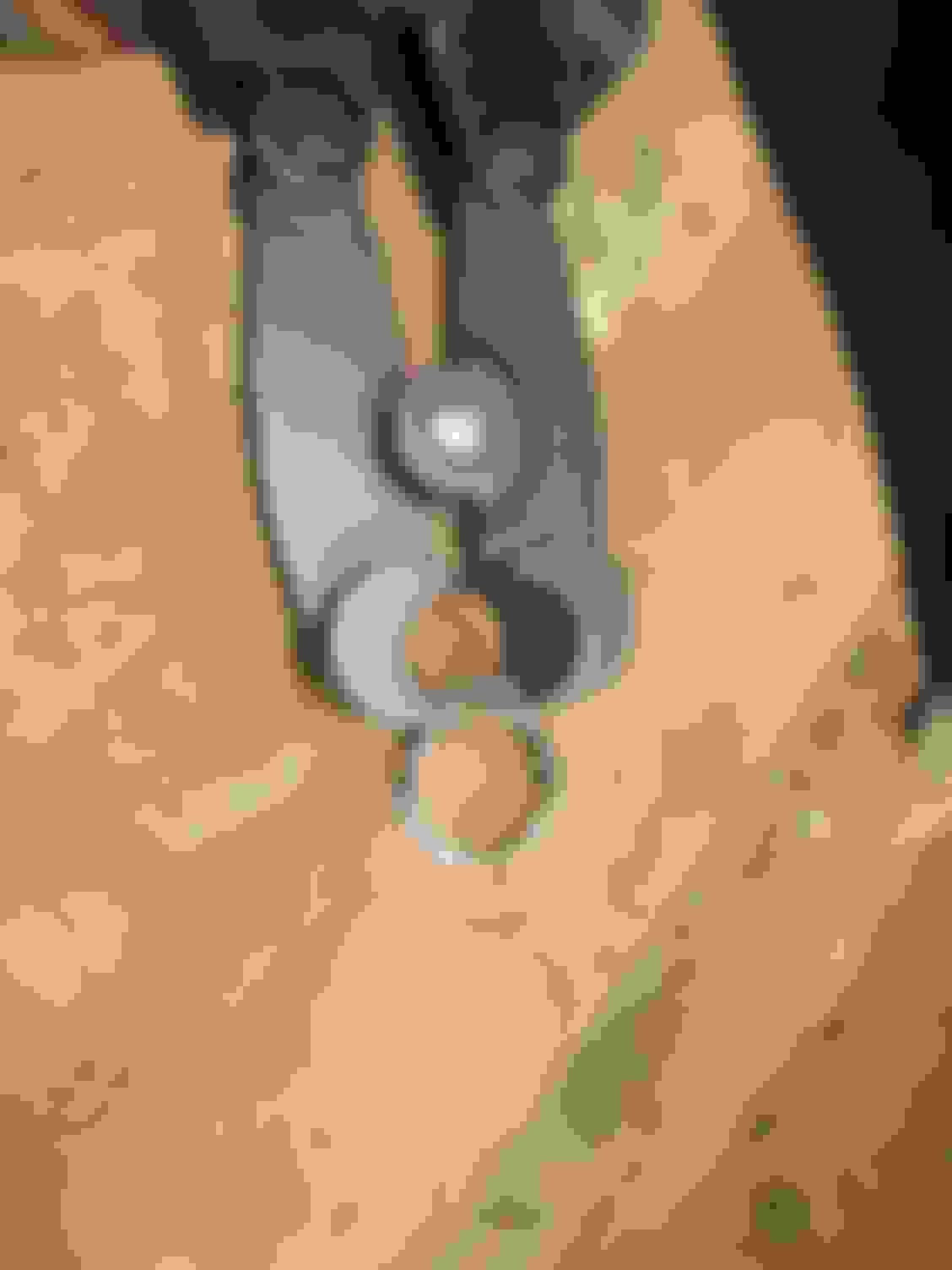
then use clips to secure the hose onto the barb. Jubilee clips (ie worm drive clips) are NOT suitable. If you have evened off the barbs as described here, use either fuel clips of Oetiker clips. I have found fuel pipe clips can loosen over time, so I splashed out and bought Oetiker clips and their tool to do them up.
Oetiker clip and tool
Closeup of Oetiker clip on the hose
Injectors installed with clips. Note that the second injector has no clip at the injector end of the hose because it is a new one and came with the hose already fitted to a non-adjusted barb.
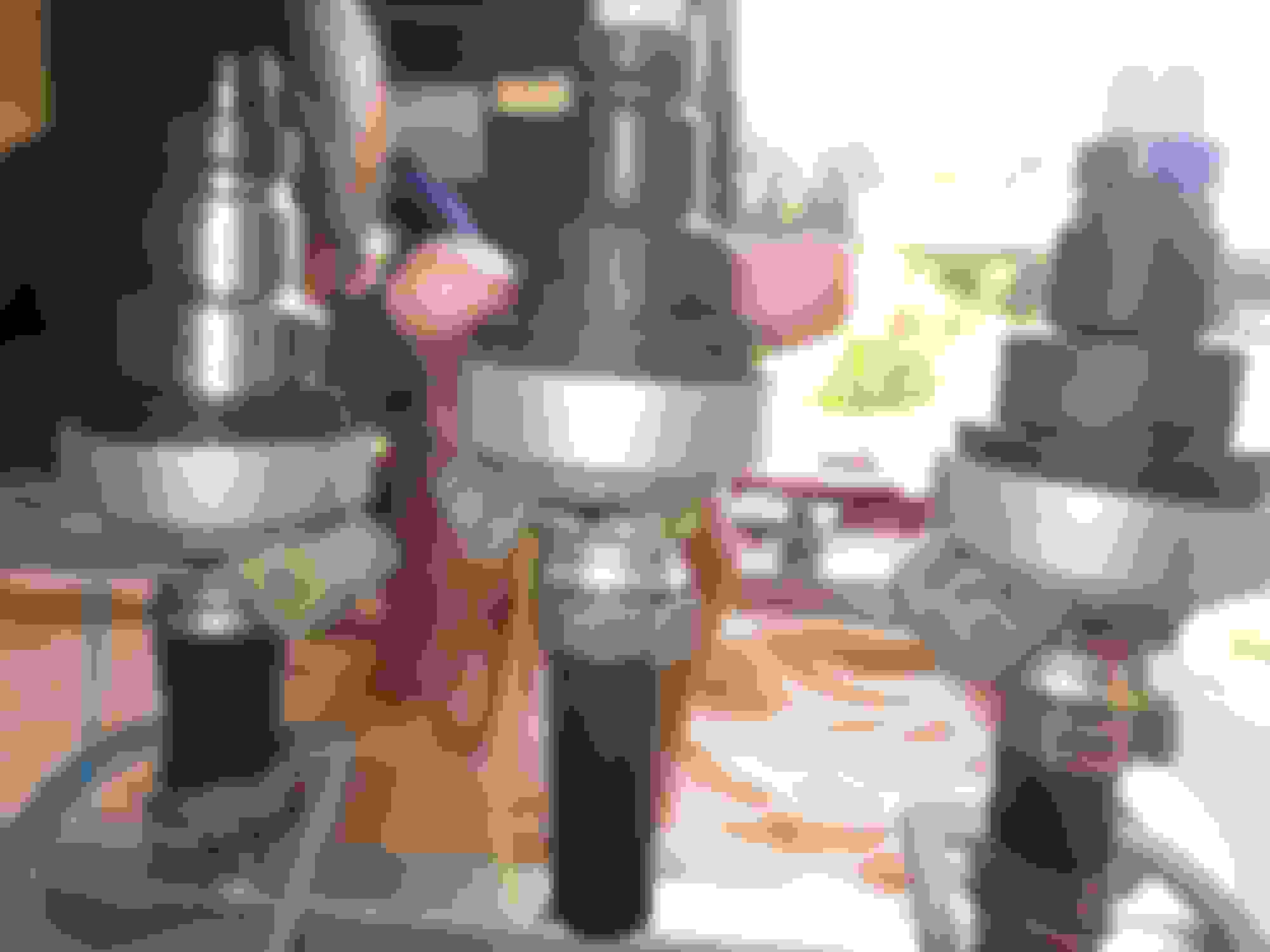
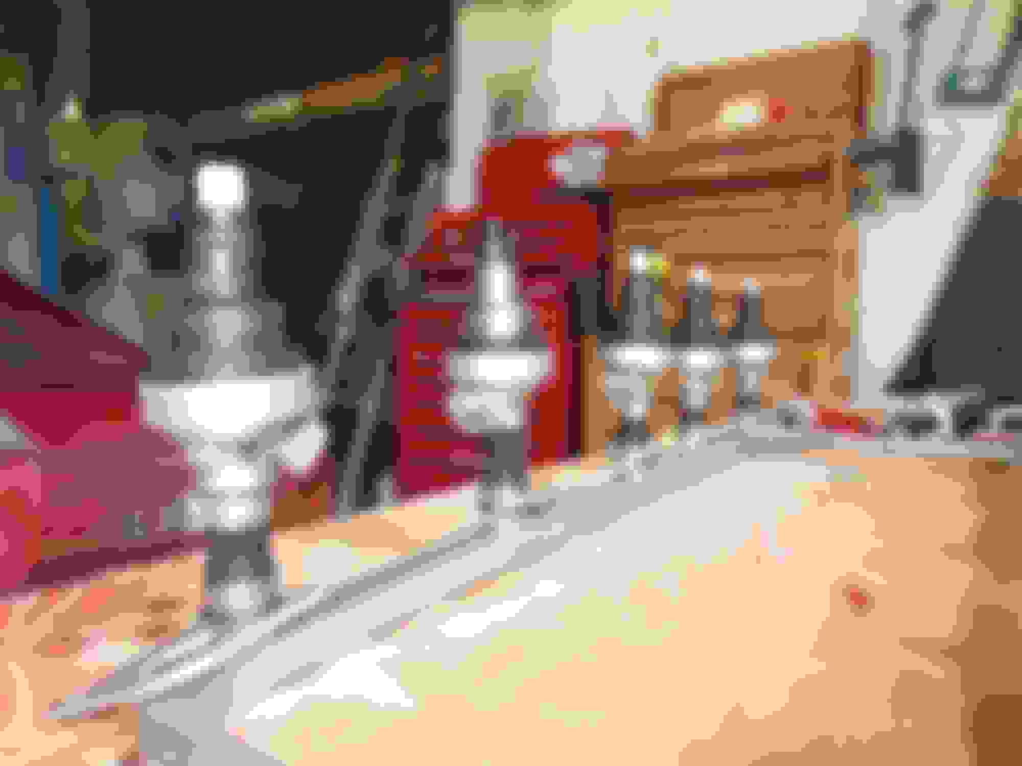
The finished rail and injectors:
Here they are all ready:
A bank done All done
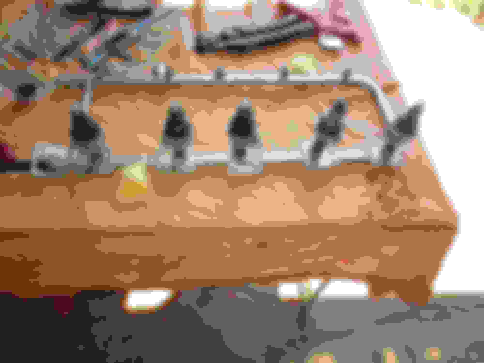
NOTE: The ORIENTATION of the connector moulding male contacts on the injectors is NOT the same down the length of the engine. Therefore great care must be take to ensure the captive fixing collars and the injectors are fitted facing the correct way. This is the factory orientation (A1 is the frontmost injector) but note also: in all cases collars must be fited so that the fixing holes on them face outwards!:
Injector A1 connector facing forward, collar indent to fit connector facing forward Injector A2 As above Injector A3 As above Injector A4 connector facing backward, collar indent to fit connector facing backward Injector A5 connector facing backward, collar indent to fit connector facing backward Injector A6 connector facing forward, collar indent to fit connector facing forward
B bank are the same.
This is injector A1 on my spare engine. Note collar indent and connector facing forward (to the right in the photo). Note fixing holes are outboard of the rail. If making up a complete replacement rail and injectors as I am, the fixiong collars are captive, so the correct orientation of the fixing collars is vital. If you make a mistake you have to remove the injector to correct it!
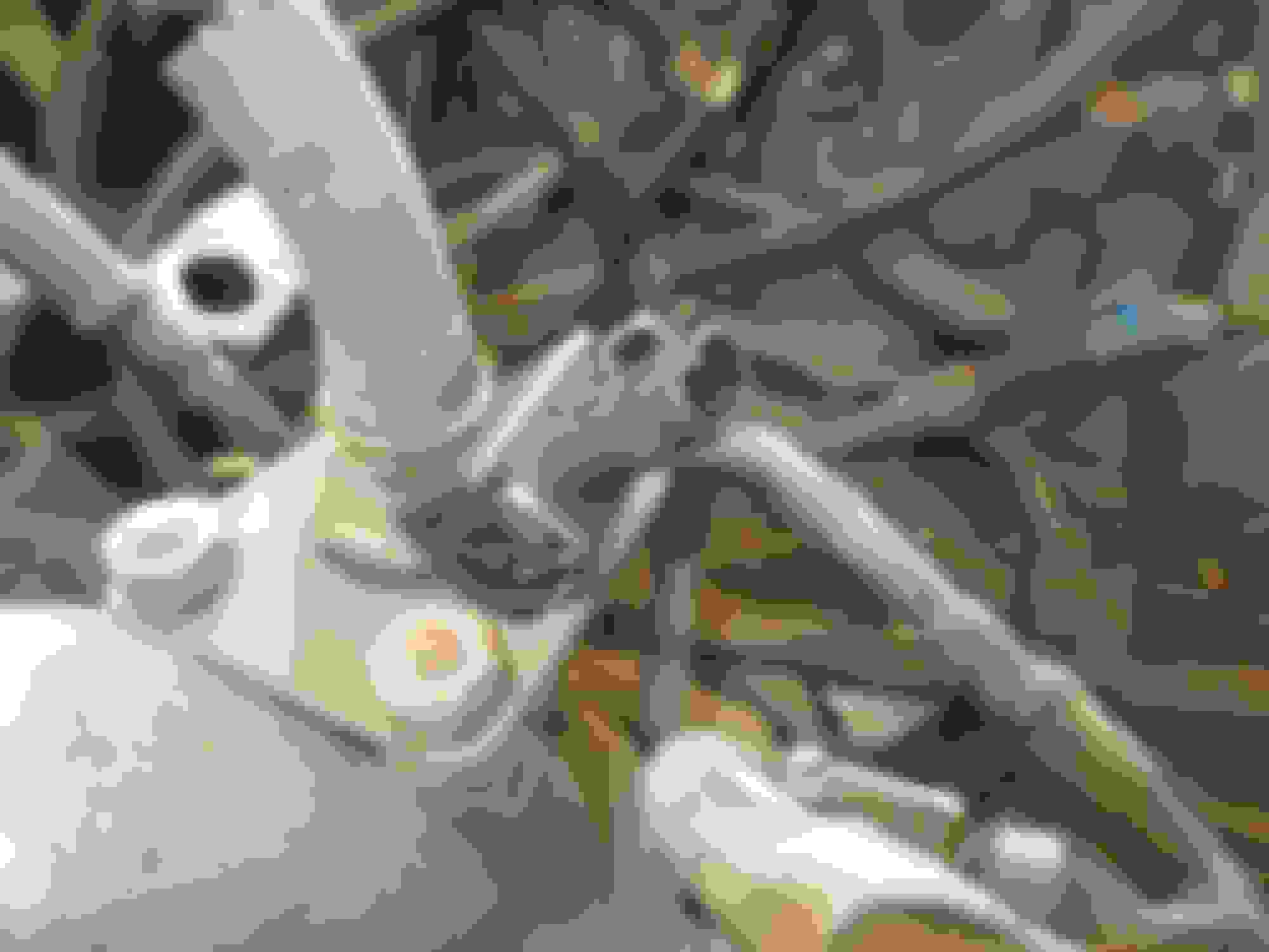
Loom to Injector conectors:
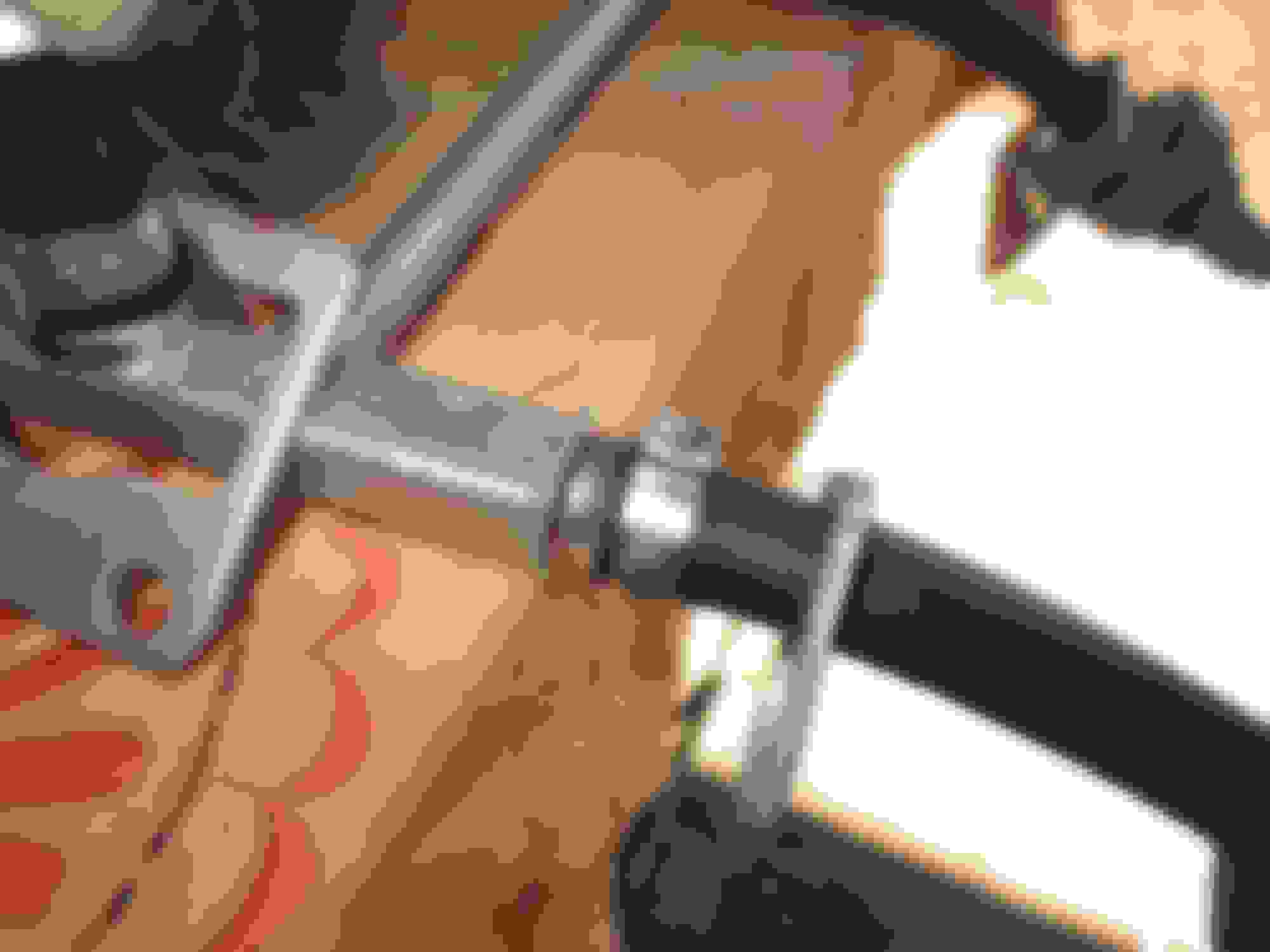
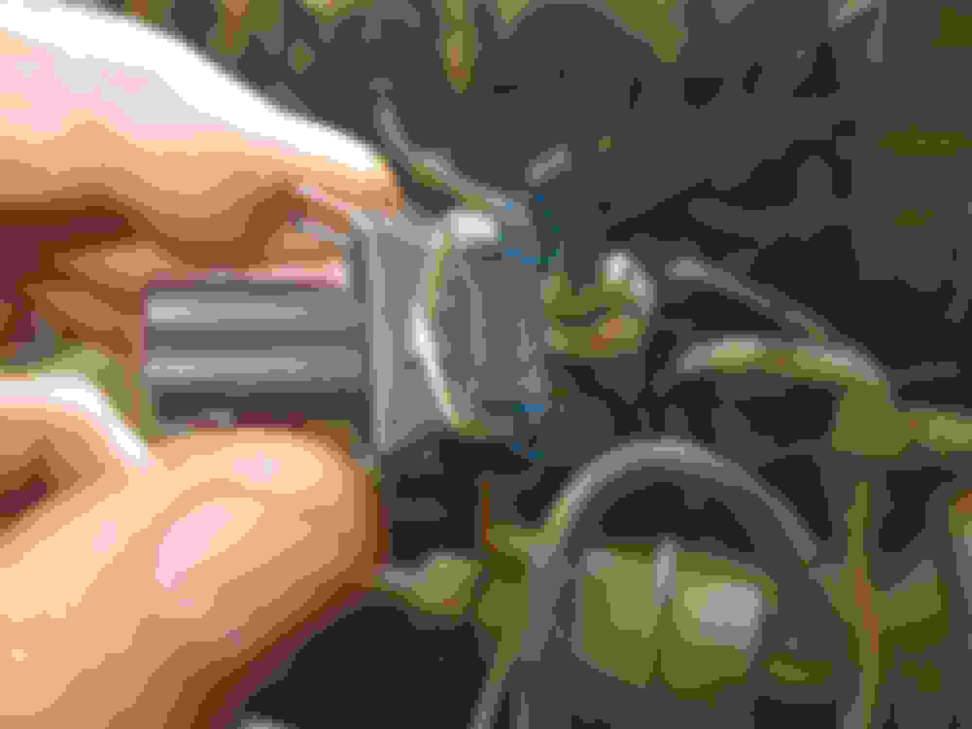
I mentioned at the start that the connectors on my loom are beginning to look past their best, and also are very hard to unclip. When I make my new loom, which will be a couple of months, I will use the clip shown in the photo above. This type of clip has sideways release metal and is FAR easier to remove from the injector to clean the contacts - which is important to do periodically for even tickover etc etc. They need a slight adjustment however, as the corners just foul the fixing collars. I ground about 1mm off the two corners so that they fit easily onto the injector with a confidence-inspiring 'click' without fouling the fixing collars:
Next installment:
In October I will build a new injector loom using silicone insulated wire for indefinite heat protection, and will use the above clips for the injectors. The beauty for me of having the rail and injectors all ready as a unit, is that I can wire up the new loom to the injectors making sure it all fits neatly and properly, with every part of just the right length and with no redundant lengths of wire in the loom.
To be continued in October...
Last edited by Greg in France; Aug 10, 2024 at 08:49 AM.
Thank you very much for this Greg. It is very helpful and will make my future project easier.
One question on the loom. I've taken your advice on sourcing the clips to the injector, but what about the loom to the main harness? Is that a unique fitting? Deutsch? Someone else?
Thank you very much for this Greg. It is very helpful and will make my future project easier.
One question on the loom. I've taken your advice on sourcing the clips to the injector, but what about the loom to the main harness? Is that a unique fitting? Deutsch? Someone else?
The loom to car connector is a moulded type and cannot be bought. If you are making a new loom you have two choices:
cut the connector off the old loom and splice it to the new loom you are making and plug it into the car harness original connector, or
replace the connector on the car loom and the new injector loom you are making.
I have ordered a set of these Deutsche connectors (not used them before) and will repace the OEM connector on the injector loom and the car loom with them. I am going to make separate looms for A bank and B bank, and will use two 4 pin connectors. Coincidentally they were delivered while I was writing this. they seem to be well made. https://www.amazon.fr/dp/B0D21VSW2M?...roduct_details
(but see post 8 below for further important info on the pins to use in these connectors).
Each bank of injectors has 2 12v power feeds (one for injectors 1, 3, 5) and one for injectors 2, 4, 6.
Similarly, each bank has 2 leads that go back to the ECU which do the actual switching. One does the switching for 1, 3, 5 and one for 2, 4, 6.
Thus 4 wires at the car to injector loom connector for A bank and 4 for B bank, hence my 4 pin connectors.
BUT, in order to feed three injectors, each of the wires must be spliced into three within the injector loom, so it can be connected to three injectors. I have decided to try these marine grade shrink-fit crimp connectors to do this job:
Time will tell if these work well or not! You will need 8 per bank (two per wire x 4 wires). They will be in effect Y shaped connectors with one arm of the Y going down to the injector and one going on to the next Y connector. Two will give you the three "arms" down to the injectors you need. Hoping you follow!
I also attach Ben Kenobi's great illustrative diagram in word format:
FYI, the main thing with fitting new connectors to the car and loom is to ensure you distinguish the power and the switching leads accurately. The colours are as follows and are easily visible still on the looms:
ALL the power leads are pink/brown (ie mainly pink with a brown stripe - that actually on my car looks like a black stripe). Therefore it does not matter which power lead does to which bank as long as two go to each bank.
The switching leads (called Peak and Hold leads) are coloured as explained in the attached pdf document. Following this should enable the use of new conectors without problems.
Ask away if anything unclear.
Thank you Greg. Yes, I thought that "to car" connector would be proprietary. I was hoping there would be a method other than splicing in new. Maybe replacing the pins, or putting new wire into the old pins? I must think on this.
Thank you Greg. Yes, I thought that "to car" connector would be proprietary. I was hoping there would be a method other than splicing in new. Maybe replacing the pins, or putting new wire into the old pins? I must think on this.
The moulded plug cannot be serviced AFAIK. But, joining the old injector side male plug to the new loom wires is perfectly OK, as the wires by the plug (say the first 6 inches or so, or more) are almost sure to be OK and not cooked. I just did not want any joins that I did not have to have!
We will see in October if that is a good idea or not...
Makes sense. Somehow, SNG Barratt has found a way to make an equivalent, but they have so many resources I do not!
One thought: Deutsch makes bot 12 point plugs and female terminals. It may make sense to change both sides with new, and then replacing in the future will not be a problem.
I agree with you on unneeded joins. That's why I'd rather repair/replace the entire connector, rather than simply splicing wires.
Me too.
Deutsche make all sizes of connectors from 2 to 12 pins, including 8 pin ones. So you can just have one 8 pin connector instead of 2 x 4 pins if you prefer.
I have done a bit more digging on the correct size of pin to use in the deutsche terminals I gave a link to in my post above. The kit I bought has stamped pins and I think solid ones would be far better. Luckily while the pins are available in different sizes, the nylon actual connector body does not change, so I have just orderd up some pins from aliexpress in this size: https://fr.aliexpress.com/item/10050...Cquery_from%3A
The main reason is that the wires on the car loom side of the OEM connector are MUCH thicker than on the injector side. The OD of these is over 3mm and I felt that the stamped terminals in the kit were too fragile and small for this gauge of wire. The pins I have ordered are much larger as well as far more robust. So I think that they will do the job, while I shall just double up the copper on the thinner injector loom side to ensure a good crimp in the larger pins.
Moulded plugs seem to be the sole preserve of the factory-made looms! It is understandable as most people will want to just buy a new loom and plug it in.
Incredibly helpful, Greg. A few months ago there was a thread "1990 OTS 5.3L Injector Numbers" that engaged an extensive discussion on injector hose replacement. A guy on You Tube (I have the subscription but can't recall the name offhand) went through his process of replacing the hoses. The ensuing discussion suggested several different approaches to the challenges involved. I now have to add your (or Grant's) suggested reduction in length of the hoses to help reduce vaporization. I have noticed on my 90 that on occasion after driving and attempting a restart that it had some strange behavior, i.e., hard restart, and extremely uneven idle (racing and chasing) that ultimately settled down when driving.
This forum, the Alfa Romeo forum, and the Mazda RX7 forum are amazing with the technical knowledge that folks share. The Volvo forum in my experience is a lot less useful. I've learned a great deal, and hopefully have added some value along the way as well, albeit nothing like some of y'all. Many thanks to a bunch of special folks.
After a longer gap than I envisaged when I refurbed the injectors, I have got started on building my new injector loom. My current loom is good, not cooked, but it is 22 years old and even though my under bonnet temps are lower than OEM and I do not do anything like the mileages I used to because fuel is so scandalously expensive, I thought injector loom renewal was a sound plan.
I decided to use silicone covered wire as that will easily stand the 80 to 90�C under bonnet maximum temperatures and should mean the loom is fit and forget permanently: https://www.amazon.fr/%C3%A9lectriqu...80&sr=8-7&th=1
I also decided to use Anchor brand step down marine grade crimp connectors so that I did not have to solder the 1 into 3 connections, as I am hopeless at it! Link here:
These are made so as to accept two of the above 18 awg wires in one end and one the other. Step down crimp connector, with heat shrink outer. In fact I used a second smaller heat shrink tube inside the Anchor one, as the silicone wires were quite thin and this gave extra grip: Extra heat shrink inside the Anchor outer heat shrink
In fact, as I discovered, these connectors will accept three of my 18 awg wires in the larger end and two in the smaller one, which greatly simplifies the loom construction. The basic difficulty of making the loom is that for each injector there is one wire that emerges from the car loom which has to feed three injectors with 12v, and one wire emerging from the car loom that has to provide those three injectors with the return 'peak and hold' signal to earth. Therefore a one-into-three splice within the injector loom downstream of the plug it connects to the car loom with is unavoidable. See the attached diagrammatic representation of this system done by Ben Kenobi, entitled "Wiring and plug diagram".
The injectors are grouped and fired in batches of three, A bank odd numbers (A1, A3, A5) and A bank even numbers (A2, A4, A6) make up two of the four groups, and their equivalent on B bank comprise the other two. Thus each bank is wired separately. The task for the injector loom maker is to make for each bank :
a sub-loom to fire the odd numbered injectors and
a sub-loom to fire the even numbered injectors.
Here is a photo of part of the A bank ODD numbered injectors, Red = 12v feed and Blue = ECU controlled earth return loom: A bank odd numbered injectors loom contruction photo (red carries 12v, blue carries to earth as commanded by the ECU).The blue has been crimped and heat shrunk, the red has been crimped but not yet shrunk
At this first stab at the loom construction I used a two-stage system to get the 1 car loom input to the three injectors:
Step down connector 1: one input from car loom; 2 outputs - one to injector A1, one to a second step down connector
Step down connector 2: one input from step down connector 1; 2 outputs to injectors A3 and A5.
Then I found out that in fact the Anchor connectors would take three wires in the output end, so this enabled me to simplify the wiring for the A bank even numbers: The three 12v output wires one for each even numbered injector
Twisted together
Inserted into the step down connector and crimped
Crimped and shrunk
The "one input three output" clearly shown. This is for the A bank even numbers 12v feed. The A bank even numbers earth return via the ECU wires are white but the loom contruction is identical.
Each sub-loom has two sets of wires, the 12v feed and the earth via ECU return which controls the injector opening and duration. So the method I used was to make first one set then the other, then make the connections to the injectors: The two wires for each injector with the connector pins crimped ready to be pushed into the injector connector housing
Injector connectors attached this photo is of the loom for the A bank even numbered injectors. Note that each of the Anchor step down crimp connectors was given a second layer of green heatshrink for extra protection as shown in the above photo and in close up here: Extra layer of green heatshrink to give strong protection to the step down connector
The two wires that will come from the car loom connector are the long ones to the right
Close up
Close up showing one in and three out of the step down connectors
Close up of the injector connector type used
So to remind everyone interested: we have made for A bank:
A 12v supply sub loom for the ODD numbered injectors (red wires)
An ECU controlled earth wire for the ODD numbered injectors (blue wires). A wire from each of these two subsets is attached to the ODD numbered injector connector pins. This ODD numbered injector subset was wrapped in either heat shrink or silicone self amalgamating tape and then wrapped in adhesive woven loom tape (a bit like sellotape but woven).
A 12v supply sub loom for the EVEN numbered injectors (red wires)
An ECU controlled earth wire for the EVEN numbered injectors (white wires). A wire from each of these two subsets is attached to EVEN numbered injector connectors. This EVEN numbered injector subset was wrapped in either heat shrink or silicone self amalgamating tape and then wrapped in adhesive woven loom tape (a bit like sellotape but woven).
These two finished subsets are shown here:
Eventually these two sublooms will be wrapped into one and the long wires will be fitted with a connector and attached to the loom-to-car-loom-plug.
After much thoght, I have decided to NOT to use new Deutche connectors for the loom-to-car-loom-plug interface. This is because it would mean removing the OEM car loom plug and that in turn would mean any future owner would not find it easy to fit a replacement OEM injector loom, should one be needed. I would be very grateful for anyone's views on this decision, for or against. I am lucky enough to have an old injector loom to cut the plug plus 5 inches of pigtail off, and I can then just use solder tubes and heat shrink to splice them to my new injector loom wires.
Last edited by Greg in France; Dec 13, 2024 at 02:59 PM.
One point I forgot to mention. How did I know what lengths to make the wires to the individual injector plugs?
Well, as described in this thread, I have ready for this new loom a complete fuel rail and injector set that I refurbished. So I offered up each piece of loom as I made it and thus created a custom loom to fit the rail and injectors with the absolute minimum of spare loops of wire:
A bank Odd numbered injectors being bespoke (custom) fitted for their new loom! Top tech home made GiF injector set stand in action.
Wow. You are truly an inspiration! The new harness is amazing.I have to say that IMHO, I would definitely consider using the original connector as you mentioned, for later ease of replacement. Or you could consider buying a spare (extra) connector of the Deutsch type, in the event that things need replacing down the road, one would be on hand! Just a thought.
I am greatly humbled by your work and your expertise!!!
Today I completely finished the loom, the last stage consisting of splicing in the moulded plug on the injector loom to match the car loom (male moulded rubber on the loom side, female on the car side).
I thought long and hard about whether to splice in the old loom's moulded plug or to fit new connectors on both sides. In the end I chickened out of the new connector idea, because that way, if ever needed, a new OEM type loom could be fitted very easily.
Attached are some photos of the splicing of my new loom to the old loom plug; I cut off my spare engine's injector loom plug with about 8 inches of pigtail. I cleaned up the plug males and the stripped ends of the pigtails by soaking them in lemon juice for 15 minutes as advised by Grant Francis (turn and bow to the Southern Cross at the mention of the Great Man's name) and they came up gleaming.
I used solder tubes for the joins, then covered those with shrink tubes, then covered the splices and exposed insulations with silicone self amalgamated tape. Finally I loom wrapped the lot. Pics below. Tomorrow or Wednesday I will remove the old loom from the existing injectors, attach my new one, and see if it all works as it should. If it does, then I shall fit my rebuilt injector rail and injectors and test the new rail for a few weeks.
New loom solder tubed to plug pigtail. The free ends were loaded with the outer shrink tube and the solder tube, then the wires twisted together and the tubes slid up into position, first the solder tube then the shrink tube.
Partially completed splices
Finished splices prior to their being wrapped individually with silicone self amalgamating tape.
Madame's mother is a great help on these occasions and here she is holding up the wrapped and completed loom she helped me finish today. Adhesive loom wrap works really well and makes a decent looking end product.
Last edited by Greg in France; Jan 6, 2025 at 09:59 AM.
#2. For those wanting to DIY this, the CORRECT EV1 connector that will fit without interference is the low profile EV1 style connector The rest will interfere due to the clip location or plastic casting.
#3. The main white silicone connector is some sort of special LUCAR connector. You can buy the bullet pins, but not the connector itself as AFAIK the OEM one is simply cast in place around the bullets.
That said, for those not wanting to go through the hassle of DIYing a harness, Andreas Eckert from Switzerland is now offering what I think is an amazing quality plug in harness with a 3D printed LUCAR style connector using MilSpec TefZel wiring, as well as a choice of several sheathing options.
#2. For those wanting to DIY this, the CORRECT EV1 connector that will fit without interference is the low profile EV1 style connector The rest will interfere due to the clip location or plastic casting.
Why I decided to use this type of connector:
is because it is FAR easier to release from the connector from the injector. I have just removed the old loom this morning, and to get the EV1s off (rail in car) you have to push a flathead screwdriver down the gap between the fixing collar and the injector to depress the release wire, which is a real pain. As you mentioned and as also said in an earlier post, it does mean filing the plastic a bit to ensure it does not foul the collar. Now, knowing what I know now, what I would do if I had not already captived the collars, would be to file the sides of the collars' rectangular indents to make them a touch wider.
We live and learn!
Tomorrow I clip on the new loom to the old rail and check the engine works properly, before swappping the rails over. Fingers crossed!
One other thing I would do if doing it again, would be to have all the injector connections facing forward, my loom will be significantly tidier than OEM as it is measured to go along the rail, not in the V; but if I had put all the injector connections facing forward, quite a significant saving of loom length, and hence even more tidyness, would have resulted
Last edited by Greg in France; Jan 7, 2025 at 06:11 AM.
Fantastic job, and I like the idea of all the injectors facing forwards for neatness!
Best of luck on the test run, I am eagerly looking forward to hearing a good report!!