When you click on links to various merchants on this site and make a purchase, this can result in this site earning a commission. Affiliate programs and affiliations include, but are not limited to, the eBay Partner Network.
so I took it upon myself to do bright *** LED lights in my gauge cluster ('88 xjs), because while the bulbs did work, they didn't work very well.
luckily the large lamps for the speedo/tach/barrels had polarity circuitry in them. thanks to diodes and such, there's no wrong way to stick them in.
the tiny bulbs for the dummy lights, that's another story; they have no indication of polarity, however they ARE polarized and don't work both ways.
no problem. plugged all 17 of those little things on my bench power, and marked the negative side of the housing with a black sharpie.
took a quick look at the copper circuits and determined that the top edge (beneath the ground bar) was ground, and that the bottom runs were +12v.
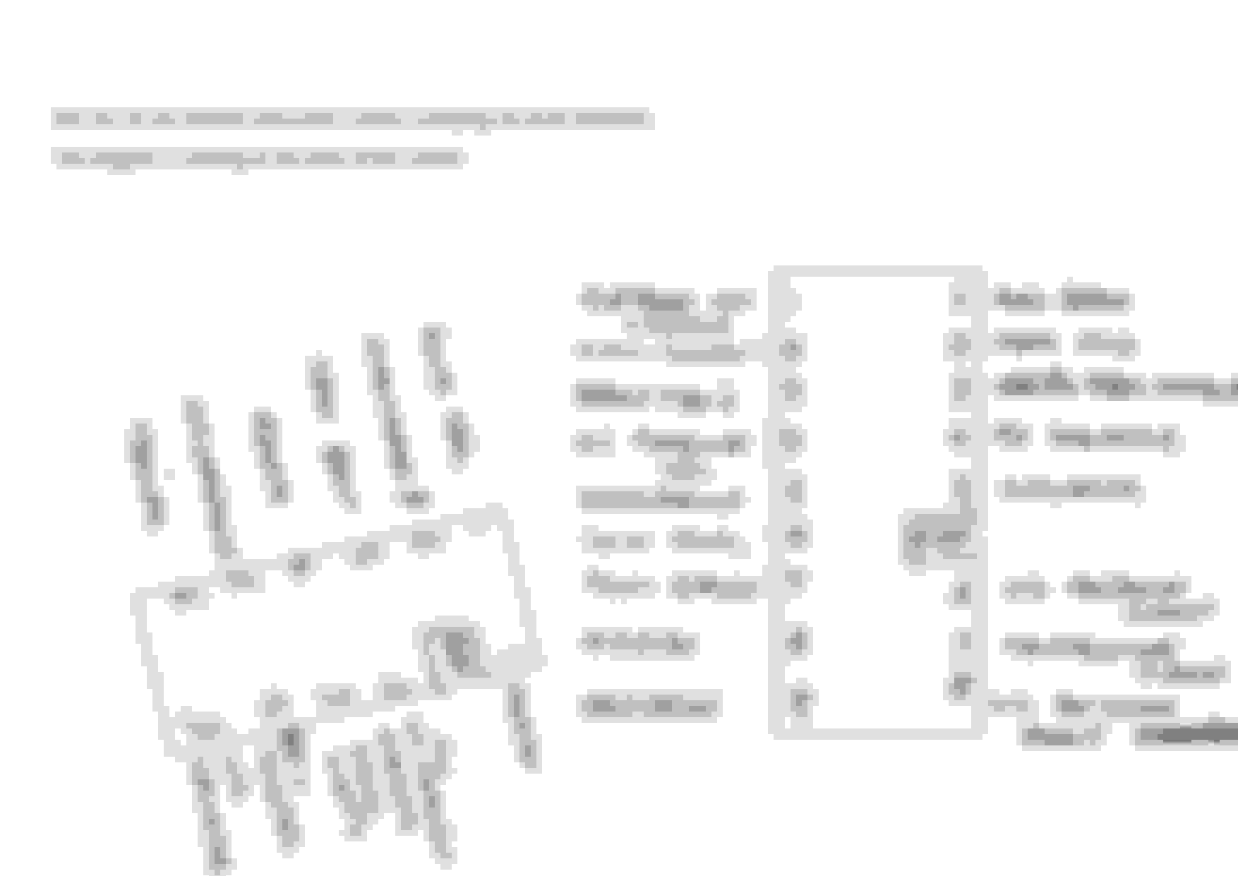
well, no turn signals, not a lot of anything. I think three lamps illuminated. I found this nice contributed pinout, but I'm curious if anybody can confirm the +/- ends of these buggers.
if not, I'll figure it out, but I'm doing this car with my 10yr old son, and he hasn't the patience.
I did say this in the writeup but I'll say it again here....DO NOT use LEDs in the alternator light, keep the old incandescent bulb here or the ALT light will not work properly, it MUST be polarity insensitive.
thanks for that. it's funny, we both did nearly identical processes. I'm curious if you noted, or if you can recall your findings about the polarity of the smaller lamps?
also, I cannot understand your comment about the ALT light? the incandescent bulbs are not polarized, but you warn to that I must use the bulb and that it must be polarity sensitive?
I also scrounged this up too, but according to this, all of my bench testing was moot because there are independently grounded circuits?
What I did when I changed most of my warning lights to LEDs, was to install the bulbs one at a time with the cluster in place (the coloured strip comes off on its own). A long nosed set of pliers works well as long as you are gentle! Then, if one did not work when I pulled out the old lamp and shoved in the LED, I could just rotate the LED. AS Warren said the alt light needs some resistance or some other electrical property that the LEDs do not have.
That�s a neat idea. I was contemplating extending the leads from the harness so I could test them in my lap lol! That sounds much harder than it needs to be.
Perhaps when it�s sorted, this will be documented well enough for the next guy to plug and go
. AS Warren said the alt light needs some resistance or some other electrical property that the LEDs do not have.
The alternator/charge light extinguishes when it sees 12v "+" on both sides. One side of the bulb has 12v "+" whenever the key is 'on'. The other side is ground..... until the alternator starts charging.
Traditionally the charge/alternator warning light needs resistance to 'excite' the circuit. I've never really gotten my head around what that means...but that's not unusual for me.
Anyhow.....
If the bulb is burned out or missing the charging won't begin until a much higher RPM (above idle speed) is reached. Anyhow....an LED probably won't give the needed resistance.
However.....
Jaguar put a resistor in the circuit parallel to the bulb. I've always presumed this was a clever way of allowing the charging system to work normally even if the bulb is burned out.
also, I cannot understand your comment about the ALT light? the incandescent bulbs are not polarized, but you warn to that I must use the bulb and that it must be polarity sensitive?
I meant the bulb in the ALT needs to be polarity insensitive. An LED will only glow one way. The ALT light needs to be turned on with + on either side of the bulb.
Doug said it well.
I will add.
The ALT light has +12volts on both sides of the bulb, once the car is started
If the alternator fails the battery side will be higher voltage than the alternator side, light will glow.
If the battery fails the alternator side will be higher voltage than the battery side, the light will glow.
They have diodes to rectify the AC to DC. - These are commonly referred to as the DIODE PACK. The easiest way to diagnose a diode failure is to measure the AC ripple on top of the DC voltage a failed diode will have the AC voltage a a few hunderd millivolts.
A regulator to control the voltage. - To diagnose a failed regulator the DC voltage will drop but the AC ripple will only be a few millivolts.
Exciting the Alternator. - This is really just biasing (turning on) the regulator. The regulator is basically a BIG *** transistor and needs certain voltages on its pins to turn it on. Most newer Alternators have a resistor to bias the regulator on, some older alternators MUST have the ALT light working to bias the regulator, in these if the ALT light fails the alternator may not excite at all.
that's a succinct explanation, and now I have a working understanding why the incandescent bulb is required. too bad they can't (or don't want to) jam diodes and such into these TINY led lamps, to allow them to operate either way. it's insignificant though, comparing the bulb to the LED when hopefully I'll not see that illuminated anytime soon anyway.
so I pulled my entire cluster circuit off.
scrubbed the copper pads with 400 grit paper, cleaned all the rust and corrosion, and reassembled with a little dielectric grease. dropped it back in with the redundant ground, and everything's great. my two takeaways from this job:
the turn indicators are constantly being fed +12V, and ground is supplied to illuminate. so those two are ground on bottom, while the rest of the dummy lights are ground on top.
the low fuel indicator does not have a common ground with the rest of the cluster. pins 6 and 8 are complete the circuit for the low fuel indicator, and nothing else.
I may put together a diagram for the next guy, but those two lights are the only tossup. that, and if you wish to test on the bench and not in the car, be prepared to flop your ground lead around.
NOTE: this view is from the rear of the cluster, not the face.
I didn't bother with the dial illumination, as the larger LEDs are all polarity-agnostic.
hopefully this will help somebody out