Track Not Available Light ON
#2
Had the same problem two years ago. Turned out to be a faulty sensor. My indie has an OBDll reader which is a lot better than mine and he was able to pinpoint which of the four sensors was bad. No problems once the misbehaving sensor was replaced. Double check the wiring harness at each sensor for corrosion.
Stu
Stu
The following users liked this post:
EZDriver (05-12-2018)
#3
The following users liked this post:
EZDriver (05-12-2018)
#4
#7
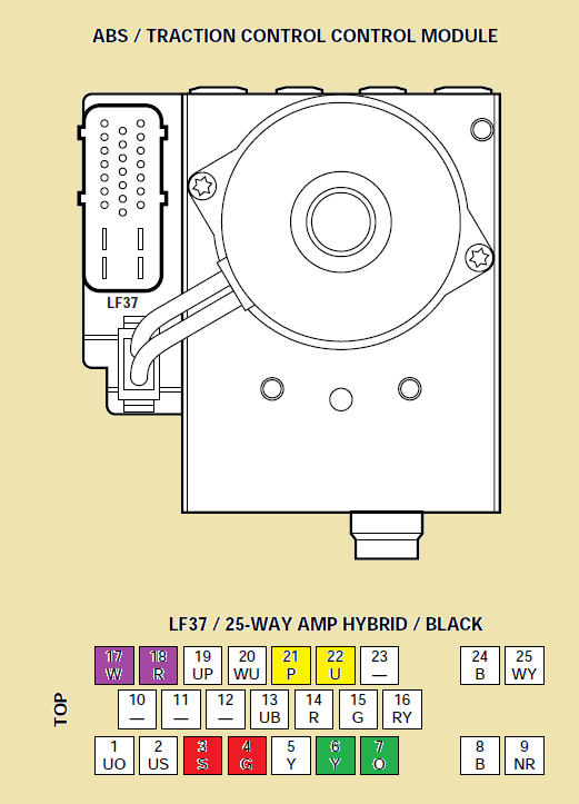
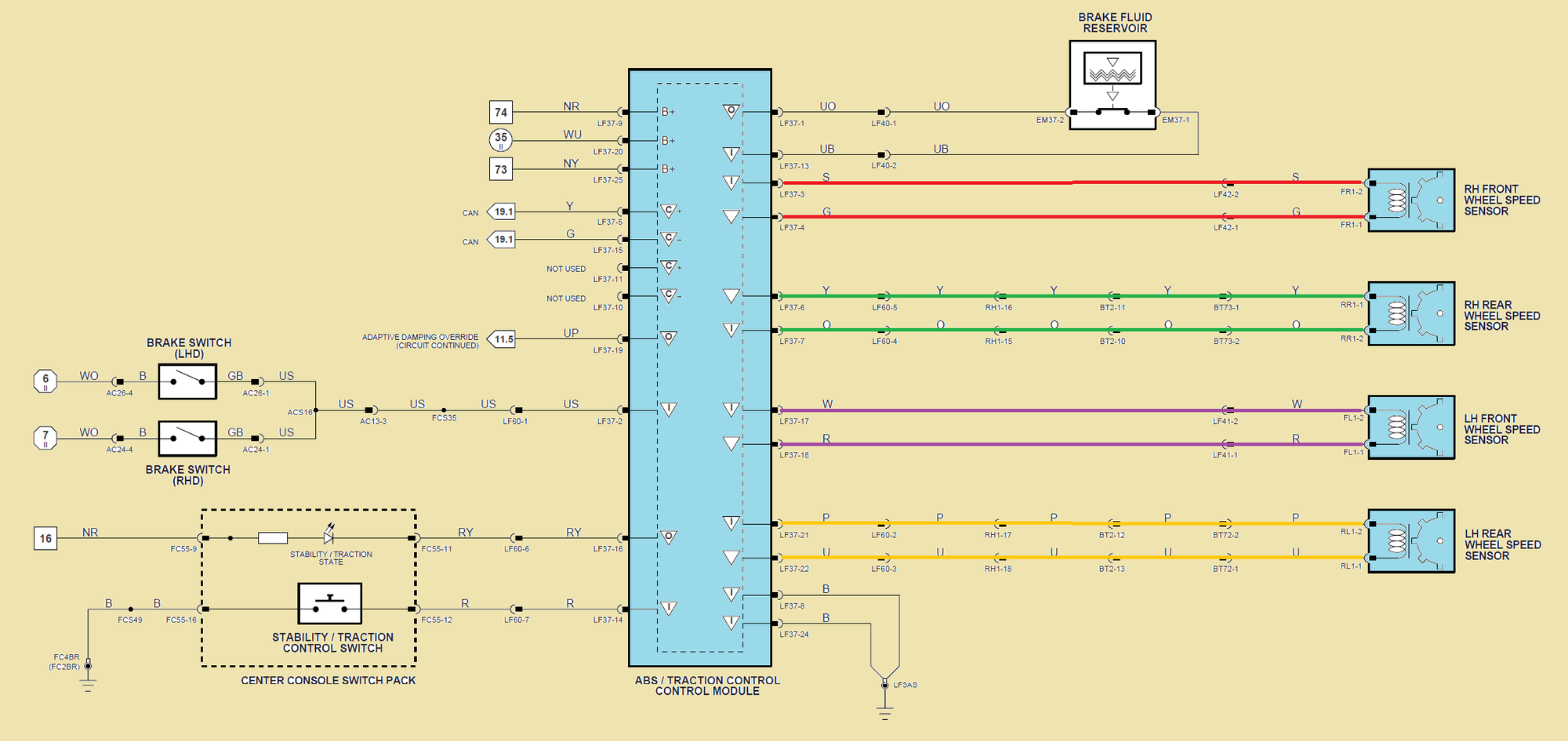
I just attempted to do the resistance check. For the life of me I can't understand the diagram. The diagram with the blocks matched exactly the connector that I have opened. The lower diagram is totally different. I went ahead and tried to check resistance through pairs of pins in the connector. All pairs checked appeared to be opened. That is no current flow, infinite resistance. What pairs in the block diagram go with which wheel sensor?
After I attempted this check. I drove the car home. The ABS loss warning was on. Then suddenly it went off for a short time. Then came back on. Is there a master plug connector between the ABS module and the individual wheel sensors? If that connector is open and for a short time made connection that would explain this latest on-off situation. What do you think
After I attempted this check. I drove the car home. The ABS loss warning was on. Then suddenly it went off for a short time. Then came back on. Is there a master plug connector between the ABS module and the individual wheel sensors? If that connector is open and for a short time made connection that would explain this latest on-off situation. What do you think
Last edited by EZDriver; 05-09-2018 at 03:07 PM. Reason: grammer
Trending Topics
#8
#10
For the 2000 XK8 see page 100 :
http://www.jagrepair.com/images/Auto.../jagxk2000.pdf
Some of the really compact digital meters ( not having a 9 volt power source ) don't have the horsepower to read down a wire .
The pairs go through up to 4 connectors for each pair .
http://www.jagrepair.com/images/Auto.../jagxk2000.pdf
Some of the really compact digital meters ( not having a 9 volt power source ) don't have the horsepower to read down a wire .
The pairs go through up to 4 connectors for each pair .
Last edited by Lady Penelope; 05-09-2018 at 05:55 PM.
The following users liked this post:
EZDriver (05-09-2018)
#11
For the 2000 XK8 see page 100 :
http://www.jagrepair.com/images/Auto.../jagxk2000.pdf
Some of the really compact digital meters ( not having a 9 volt power source ) don't have the horsepower to read down a wire .
The pairs go through up to 4 connectors for each pair .
http://www.jagrepair.com/images/Auto.../jagxk2000.pdf
Some of the really compact digital meters ( not having a 9 volt power source ) don't have the horsepower to read down a wire .
The pairs go through up to 4 connectors for each pair .
Thanks again.
#12
The ABS light will not come on until the 3rd fault / cycle and won't unlatch until it reaches 12.5 MPH . So it can be troublesome to troubleshoot . Clean the connectors that you can get to easily . I didn't exercise my transfer rights to Dallas with American when they closed STL and MCI . Admired your work years before on the ME262 . Oak Park H.S. ?
The following users liked this post:
EZDriver (05-12-2018)
#14
From what you have said you checked continuity on the four wheel circuits. How did you do that exactly. I must be doing something wrong. I have a 9v tester with seven ranges the go from 200 to 2000m ohms. I have even pushed small pins in the female plugs in order to make good contact and nothing shows up on the meter. In other words every measurement indicates an open circuit. I believe that if I bought a brand new Jag module and installed it the system would not work.
Any help would be appreciated.
#15
I agree with you, in my case the continuity checks were straightforward and were within tolerance. Why none of your 4 sensors give any reading is mystifying. you just check as Penelope showed. You check the pigtail, not the socket. Identify pins by the number and if no continuity, i would unplug each sensor in turn and use a long jumper wire back to the pigtail and see if the harness is bad.
The following users liked this post:
EZDriver (05-12-2018)
#16
Another way to look at it is to remove the connector from the ABS module and locate the Blue / Orange wire in the corner socket of the connector . This will be the # 1 socket and you can put a bread twisty on the wire so when you handle the connector you don't have to keep reorienting yourself . Keep in mind the socket location is a mirror image of the pin location in the wiring guide .
Another way is to hunt for the 2 different pairs in the 2 corners of the small sized socket group of 25 . Once you find these 2 pairs the other 2 pairs will follow .
Another way is to remove the sensor connector and read it backwards to find the socket location . Then you would put the sensor connector back together and read it from the ABS module connector through the reconnected sensor .
They should read about 1300 ohms .
The following users liked this post:
EZDriver (05-12-2018)
#17
Hi Lady,
I got the plug diagram figured out right away. Just got confused trying to match it to the internal wiring diagram. However, I was never able to get any reading using the ohm meter on any of the four wheel sensors. I checked the continuity of the sensors themselves and they were OK.
Yesterday I was able to locate a shop that had a good scanner. They scanned the system and came up with the code of C1095 Pump motor circuit failure. Right after I left the shop the system went normal. No warning light, Track Not Available. It stayed normal all day. Then this morning on initial start up, Track not available. Warning stayed on all day.
My next question concerns the pump. Is that round object on the side of the module the pump? It seems like it might just be worn brushes on an electric motor. I am wondering if I can just buy a new pump. Or it might be just some bad wiring connection like I have heard about from other members.
Looking forward to hearing from you on this new turn of events. I hope Bob also responds.
Last edited by EZDriver; 05-12-2018 at 10:37 PM.
#18
the C1095 usually concern cold solder of a key point inside the module that many have experienced and repaired their self . Many post and pics on the mater as the X100 , X300 , and X308 are pretty similar .
See the pic on post # 15 with the hole cut and you can see the 2 large solder points in the top of the hole
https://www.jaguarforums.com/forum/x...otocol-195383/
and for the little bit different X300
https://www.jaguarforums.com/forum/x...c-fault-44272/
Editing
See the pic on post # 15 with the hole cut and you can see the 2 large solder points in the top of the hole
https://www.jaguarforums.com/forum/x...otocol-195383/
and for the little bit different X300
https://www.jaguarforums.com/forum/x...c-fault-44272/
Editing
Last edited by Lady Penelope; 05-12-2018 at 11:01 PM.
The following users liked this post:
EZDriver (05-12-2018)
#19
Thanks again.
#20
The hole location is different between the different models .
Had a problem with the barber pole not showing at M.95 and turned out to be the engineer changed from a descrete air / ground shift to a digital in the upgraded air data computer .
Last edited by Lady Penelope; 05-12-2018 at 11:16 PM.
The following users liked this post:
EZDriver (05-12-2018)


