Jaguar Forums - Jaguar Enthusiasts Forum
  • LOG IN
  • REGISTER
  • Forums
    • General Jaguar Forums
      • New Member Area - Intro a MUST
      • Jaguar Forums Feedback & Suggestion Center
      • General Tech Help
    • Jaguar Models ( Current )
      • XF (X260)
      • F-Type ( X152 )
      • XE ( X760 )
      • E-Pace
      • F-Pace (X761) / C-X17
      • I-Pace EV
    • Jaguar Models ( Modern )
      • XF and XFR ( X250 )
      • XJ ( X351 )
      • X-Type ( X400 )
      • S-Type / S type R Supercharged V8 ( X200 )
      • XJ XJ6 / XJ8 / XJR ( X350 & X358 )
      • XJ XJ8 / XJR ( X308 )
      • XJ XJ12 ( X305 )
      • XJ XJ6 / XJR6 ( X300 )
      • XK8 / XKR ( X100 )
      • XK / XKR ( X150 )
    • Jaguar Models ( Classics )
      • Mark V - X 420G
      • MKI / MKII S type 240 340 & Daimler
      • XK120 XK140 XK150
      • E type ( XK-E )
      • XJ6 & XJ12 Series I, II & III
      • XJS ( X27 )
      • XJ40 ( XJ81 )
      • XKSS
      • XJ220
    • Other Jaguars
      • Other Jaguar Models / Concepts / Replicas
    • Diesel variants
      • Diesel variants - All models
    • Non Jaguar vehicles
      • Non-Jaguar Vehicles
    • Brand Review
      • Jaguar Press release
      • Jaguar Customer Relationship Centre
      • Jaguar Engines & transmissions
      • Wheels / Tires, Suspension & handling
      • Interior
      • Exterior
      • Audio/Visual Electronics
      • Detailing / Car care
      • Motorsports
    • Jaguar Classifieds
      • Marketplace
      • PRIVATE For Sale / Trade or Buy Classifieds
      • VENDOR 'For Sale' Classifieds
    • Regional
      • US Northeast
      • US Central
      • US Southwest
      • US Western
      • US Northwest
      • US Midwest
      • US Mid Atlantic
      • US Lower Atlantic
      • US Southern Midwest
      • Canada
      • Mexico, South America
      • UK & Eire
      • Europe
      • Australia - Queensland
      • Australia - New South Wales / ACT
      • Australia - Victoria / Tasmania
      • Australia - Western
      • Australia - South / NT
      • New Zealand
      • Other Areas
    • Official Site Sponsors
      • VENDOR Threads
    • General Interest / History
      • Sights N Sounds
      • Photography
      • Forum announcement archives / Forum History
      • Jaguarforums Merchandise
      • Memorial Section
  • News
  • Marketplace
    • Vendor Directory
    • Become a Vendor
    • Member Marketplace
    • Vendor Marketplace
    • Site Store
  • New Posts
  • Tools
    • Car Payment Calculator
    • Tire Rim Calculator
    • Vin Decoder
    • Recalls
    • Technical Service Bulletins (TSBs)
    • Members List
    • Live Feed
  • Gallery
  • View Dark Mode
    • Please register or login to enable Dark Mode.
  • Log In
  • Register
Jaguar Forums - Jaguar Enthusiasts Forum
    • Threads
      • Advanced
Dark Mode

Please register or login to enable Dark Mode.

Log In

Forgot your Password?

By logging into your account, you agree to our Terms of Use and Privacy Policy, and to the use of cookies as described therein.
or
 
  • Recent
  • Commented
  • Albums
  • My Pictures

Peter_of_Australia's Photos

View Profile
Sort:
Commented
  • Most Recent
  • Most Comments
  • Albums
  • Photos
And here we go
And here we go
0 2022/11/19 04:55:48 Peter_of_A
Double-sided 3M-like clear sticky tape...
0 2022/11/19 04:55:46 Peter_of_A
And when ever doing straight cuts add this "special feature" to reduce vibration.
0 2022/11/19 04:55:44 Peter_of_A
I am not sure if anybody ever attempted before to cut out a tiny circle with an angel-grinder - but it is possible - obviously wear a full face-mask.
0 2022/11/19 04:55:41 Peter_of_A
0.4mm stainless steel. First I used cardboard to make a template over the 2 plastic parts (2 attempts), then I transferred the shape onto the stainless steel.
0 2022/11/19 04:55:39 Peter_of_A
That's the result... And I just love the Jag-emblem in the middle. My inspiration for that was the Ferrari horse in the same spot on a Ferrari.
0 2022/11/19 04:55:36 Peter_of_A
It's a 1976 Jag
It's a 1976 Jag
0 2022/11/12 03:47:12 Peter_of_A
It's a Jag Ute project car
0 2022/11/12 03:47:10 Peter_of_A
Van
Van
0 2022/11/11 01:32:53 Peter_of_A
On the back it says on the left: "This is a (Mazda) E2000", and on the right: "...thus it's an E-Type  ;) "   and I added the jumping leaper emblem... On the front it says just E2000 and on the right just "E-Type  ;) "
On the back it says on the left: "This is a (Mazda) E2000", and on the right: "...thus it's an E-Type ;) " and I added the jumping leaper emblem... On the front it says just E2000 and on the right just "E-Type ;) "
0 2022/11/10 15:17:45 Peter_of_A
Originally this ride-on came in orange - so I just had to respray it - so which colour, if not racing green?  ;)
Originally this ride-on came in orange - so I just had to respray it - so which colour, if not racing green? ;)
0 2022/11/10 03:57:59 Peter_of_A
Better!
Better!
0 2022/11/08 03:48:41 Peter_of_A
And while others release the tension of the tensioner (when installing the new drive belt) from underneath, I did it from the top, making my "special tool" even more special: After pulling the ratchet via the pipe extension up, I stuck a huge screwdriver into that pipe to arrest the tensioned in that position, which allowed me to very comfortably and slowly bring the drive belt into position (the correct position after 1 failed attempt in the wrong position (see top of thread).
0 2022/11/08 03:48:40 Peter_of_A
And another "special tool" to fix pulley 6. Btw.: the space is that limited around pulley 2 and 3 that it is possible only to just get a special tool in to loosen or fasten the bolt - the rest of the action (screwing out and in) is best done with the two pointer-fingers of your two hands.
0 2022/11/08 03:48:38 Peter_of_A
All 3 pulleys are "better" now... ;). Btw.: Since removing the 3 pulleys form the car, I took special care not to mix up the bits and pieces (bolts / washers, etc.) associated with each pulley.
0 2022/11/08 03:48:36 Peter_of_A
This would be the easiest and best way to get the new bearing back into the pulleys: A hydraulic press, and I press the new bearing in with the old one on top, and then I remove the old one afterwards again.
0 2022/11/08 03:48:34 Peter_of_A
I did the research at home to make life for the guys at the bearing shop easier: both smooth idler pulley had the same bearing (I found that it is 6203-2rs, they sold me 6203 C 2HRS by FAG), and the grooved one (I found that it is 6303-2rs, they sold me 6303 C 2HRS by FAG).
0 2022/11/08 03:48:31 Peter_of_A
Left the bearing of pulley 6, and right of the one, which was stuck completely: No. 2. Both obviously disintegrated already. The bearing of pulley No. 3, the grooved one, did not look that bad, but I swapped it as well - for good measure.
0 2022/11/08 03:48:29 Peter_of_A
That's how to remove the pulleys.
0 2022/11/08 03:48:27 Peter_of_A
That is the cleaned up idler pulley no. 2, already with the new bearing - but you can still see the discoloration at the inner backside: That spot got really hot, while the pulley did not rotate anymore (friction heat).
0 2022/11/08 03:48:25 Peter_of_A
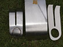
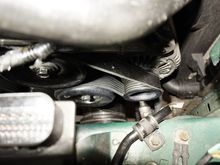
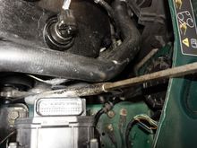
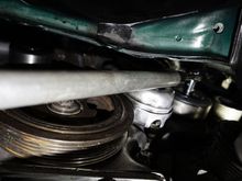
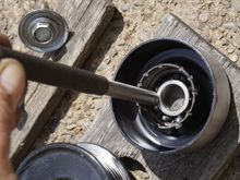
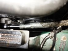
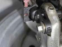
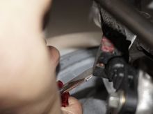
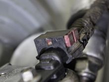
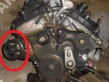
...every mm extra space helps: I removed that connector, to get another mm of access-space. And as you can see I created another "special tool" to release the tension by using a "welded solid" 3/8 ratchet and a pipe extension to move the tensioner to the back of the car. There is not sufficient space for a normal ratchet, hence I used mine, which broke a long time ago and I welded the mechanism together (results in less height). HOWEVER, I saw meanwhile, that you do that normally from underneath
0 2022/11/08 03:48:23 Peter_of_A
I had to be inventive and create various "special tools", which would allow be to loosen the hex-bolts of the three idler pulleys. Accessing some from above and some from below - and "below" means: Remove the right frt. wheel (plus I removed the rotor and brake disks for the purpose of cleaning the lot), and then remove the plastic splash shield behind the wheel.
0 2022/11/08 03:48:21 Peter_of_A
And this is a picture, where you see how NOT to install the drive belt later on. It is very tempting to do it that way, as it seems more logical, plus, you only note the difference when you see the right and wrong way next to each other. Doing it the wrong way results in less tension on the belt and rubs the belt against itself to the effect that your ears are being blown off...
0 2022/11/08 03:48:19 Peter_of_A
As it is not possible to take a picture of all the pulleys due to the space restriction, and as it really difficult to find a sketch on the net, I created a sketch myself - more a Picasso than a Rembrandt, but it does the trick. I removed the idler pulleys 2, 3 and 6.
0 2022/11/08 03:48:16 Peter_of_A
...but there is not much point in explaining exactly how I did that, because this was a pointless exercise: On the S-Type that DSC-module cannot be opened and I cannot access the PCB. Thus, I put it straight back in. I think what I saw on the net regarding that PCB must have been on the XJ8...
0 2022/11/05 04:36:48 Peter_of_A
ANNOYINGLY the ABS & Cruise faults were still there. In my extensive research on the net I saw that it is possible that the PCB of the ABS/DSC-module (the elk-test-module  ;) ) could have cold welds in need of rewelding. Thus, I actually managed the near impossible to remove the black-box DSC-module from the  "octopus", without actually removing any brake-lines...
ANNOYINGLY the ABS & Cruise faults were still there. In my extensive research on the net I saw that it is possible that the PCB of the ABS/DSC-module (the elk-test-module ;) ) could have cold welds in need of rewelding. Thus, I actually managed the near impossible to remove the black-box DSC-module from the "octopus", without actually removing any brake-lines...
0 2022/11/05 04:36:46 Peter_of_A
Here I measure 2.5 Mega Ohm on each of the brand new sensors. One old one measured 0.7MOhm and the other one started the measurement at that same level, but quickly went down to zero MOhm. I assume one or the other was broken. Anyway, I had now the new ones.
0 2022/11/05 04:36:43 Peter_of_A
And this is that connector. I measured (with ignition on) the full battery voltage between those 2 pins, which tells me that the wiring is OK.
0 2022/11/05 04:36:41 Peter_of_A
After that pin has been pushed thru it is extremlu easy to lift the connector off.
0 2022/11/05 04:36:39 Peter_of_A
This is being done with a screwdriver.
0 2022/11/05 04:36:38 Peter_of_A
Those connectors to the ABS speed sensors on the rear axle are a bit tricky to open. The connecots on the left and right are identical, i.e. on one side, the red "pin" need to be pushed outwards, on the other side inwards.
0 2022/11/05 04:36:36 Peter_of_A
0 2022/11/05 04:34:42 Peter_of_A
0 2022/11/05 04:34:40 Peter_of_A
0 2022/11/05 04:34:38 Peter_of_A
0 2022/11/05 04:34:36 Peter_of_A
0 2022/11/05 04:34:34 Peter_of_A
0 2022/11/05 04:34:32 Peter_of_A
0 2022/11/05 04:34:29 Peter_of_A
Everything is extremely tight in that area. Thus, I can't properly see it - that picture is from the internet: What is the function of that pulley in the red circle? What is powered via that pulley?
0 2022/10/27 17:33:59 Peter_of_A
I replaced the old fog lights with those fance LED fog lights with LED DTRL halo. Their cables end in the opposing connector to the one in the previous picture.
0 2022/10/24 00:00:20 Peter_of_A
First
Page
21 of 24
Last
Go To
Page
  • 1
  • ...
  • 18
  • 19
  • 20
  • 21
  • 22
  • 23
  • 24
21 of 24
Go To GO
Go to page of 24 pages
  • 1
  • ...
  • 18
  • 19
  • 20
  • 21
  • 22
  • 23
  • 24

Top
Jaguar Forums - Jaguar Enthusiasts Forum
  • Contact Us
  • FAQ
  • Archive
  • Advertising
  • Cookie Policy
  • Privacy Statement
  • Terms of Service
  • Your Privacy Choices
  • Manage Preferences

© 2026 MH Sub I, LLC dba Internet Brands

Follow Us        


When you click on links to various merchants on this site and make a purchase, this can result in this site earning a commission. Affiliate programs and affiliations include, but are not limited to, the eBay Partner Network.