When you click on links to various merchants on this site and make a purchase, this can result in this site earning a commission. Affiliate programs and affiliations include, but are not limited to, the eBay Partner Network.
I have a 2000 XJR seat with the seat module LNC2160AD. I'm trying to transplant the seat to a 1968 Jaguar MK2. Is it possible to control the seat without a CAN system. Here are pics of the seat connectors and wiring.
guanshee, I have helped a few others do what you are looking at doing. I am on travel, so, give me a few days and I will look up what wires you need to put together to make the seat work in the other car. If you do some looking under seat wiring and my name, you might find some useful information and atleast give you a starting point. There should be 3 black wires that you will need to find. Those will be your grounds. By the way, do you know if the seat is a 10 way, 12 way, etc seat? Things vary a little with options like this.
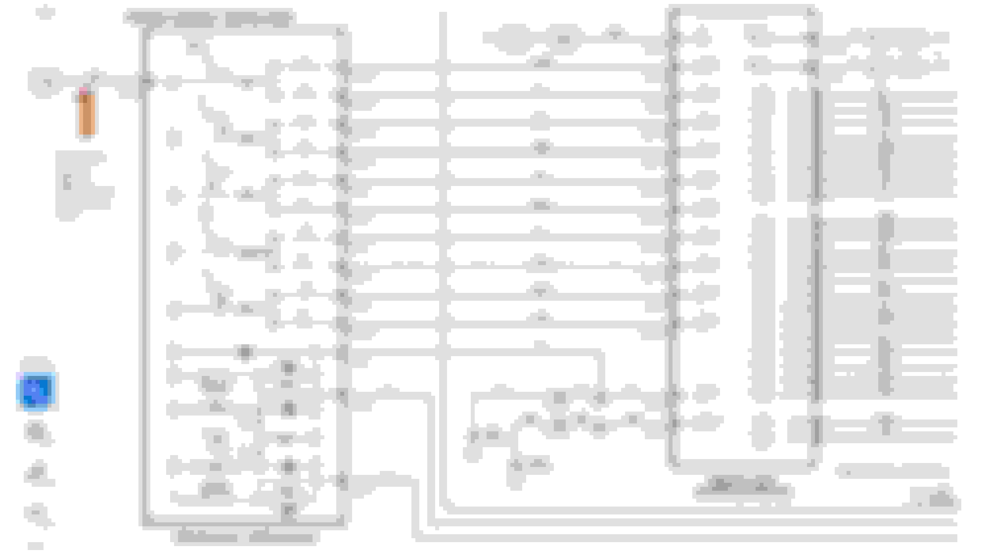
Thanks Thermo. I believe this is a 16-way seat. Here is a pic of the driver seat module connector diagram and I have all 3 plugs. As from the original picture, I'm not sure what the white connector plug represents and of its colored wires.
Last edited by guanshee; Jul 18, 2024 at 01:14 PM.
I did have this guide which is where I pulled the connector diagram. Here is my recent update. I connected all the brown (N) color combination wires on both connectors SD1 and SD3 but still no response from the seat switch control. With the connectors connected to the seat module, I was able to get all the motors to respond with the exception of the lumbar pump, if I applied power (+) with a probe to pins 9 to 16 on the SD1 connector while connected to the seat module. I still need the motors to respond via the seat switch controls and am not sure why they are not responding.
I got things working with the seat switch (seat movement, headrest, and lumbar pump). Here are the wiring spice connections to do while connectors are plugged into the seat module, which are simple:
Connect the GU (Green/Light Blue) wire on the white plug which connects to the seat switch control to (+).
Connect pin 5 (NR - Brown/Red) wire on the SD3 connector to (+).
Connect the black wire from the white plug to (-) ground.
I hope this helps others. I've attached pics for reference.
Last edited by guanshee; Jul 18, 2024 at 04:16 PM.
Ok, having the above diagram, I am going to tell you how to wire this up.
The wires going to ground: Follow the pin numbers, do not worry so much about the wire colors as we have a drawing from a different vehicle and the wire colors may be different.
SD3 (white plug) Pin 1: Black wire wit ha pink stripe
SD3 Pin 2: Black wire - may need to follow this back a little bit as it appears to split and go to both chassis ground and the ground on the switch pack to hte side of the seat. Diagram is saying black, but the pictures are saying brown. Will have to look at whatever wire is in DS3 PIn 2 spot.
You need battery power to :
Sd5 PIN 9 (plug going to seat switch pack - green wire with a blue stripe
SD3 PIn 5 - Brown wire with a red stripe