
V12 injector loom DIY build with pictures !!!


Thread Starter
|
Senior Member


Joined: Mar 2008
Posts: 821
Likes: 502
From: Gloucester UK
i have been in the process of getting parts together to rebuild the injector loom on my V12
this entailed getting the correct Bosch injector plugs, some heat resistant wiring, some cable sleeving and heat shrink and i also opted for some new 4 pin plugs to replace the original moulded 8 pin Lucas plug behind the offside headlight..
the cable is 16awg 200�C 600v , silicone , the only place i could get it was from Hong Kong by the mtr........ and you need 15mtrs of red and 15mtrs of black , more colours would make it better for identification , but is not really necessary.
so , i now have all the parts , and i decided to start the project today ,
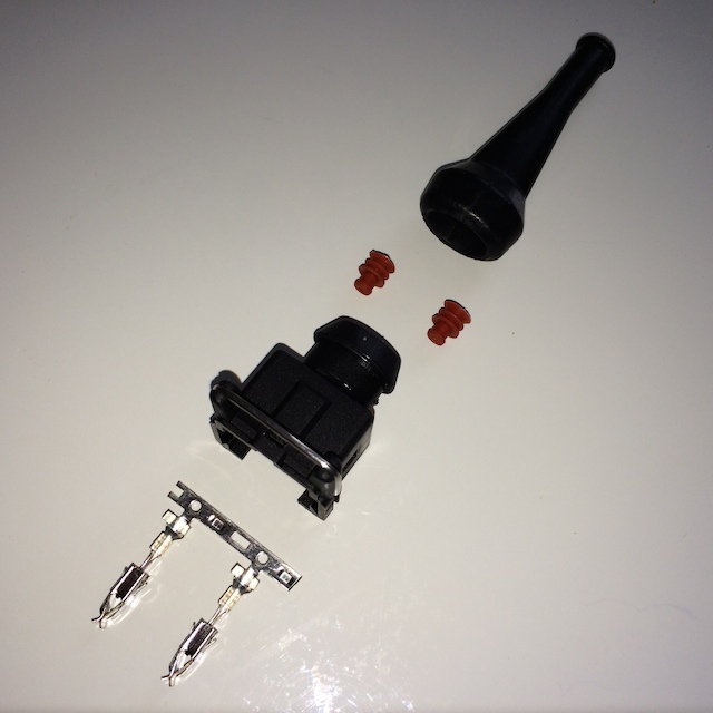
below are the plug components in order of assembly
 [/URL]
IMG_1688 by MyPix on Talk Photography
next is to measure out the runs ,
there are twelve injectors , with four firing circuits , long runs to A6 and A5 run back to the 8 pin connector , and also runs from B6 and B5 back to the 8 pin connector, the rest of the injectors splice into these looms with three injectors on each one ,
so , A6 , A4 and A2 , with A5 , A3 and A1 on the A bank ,
B6 , B4 and B2 with B5 , B3 and B1 on the B bank
schematic taken from Bernard Embdens site
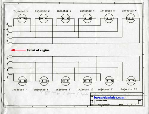
schematic3 by MyPix on Talk Photography
onto assembly
get a pair of wires measured from B6 to the 8 pin plug , and push over the boot , and the pair of connector seals ,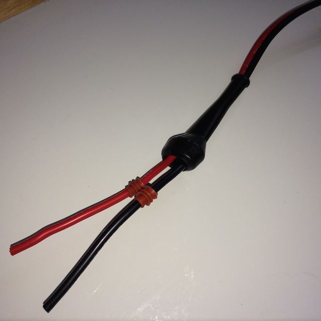
IMG_1690 by MyPix on Talk Photography
then strip the ends of the wires by about 3mm
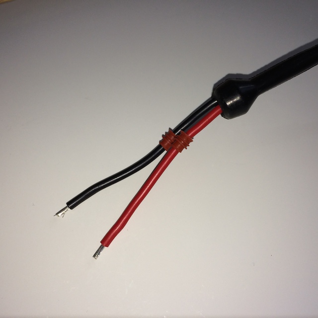
IMG_1691 by MyPix on Talk Photography
then crimp on the pair of terminals, i decided not to solder as these are designed to hold perfectly well with just crimping , a standard automotive crimping tool can do this ,
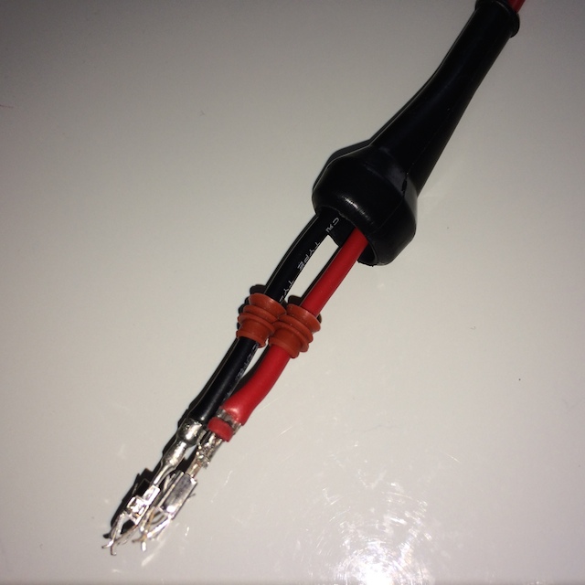
IMG_1692 by MyPix on Talk Photography
then push on the plug so the terminal clicks into place, they will only insert in the correct orientation , so idiot proof ( i hope )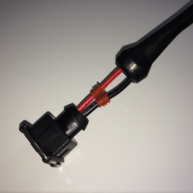
IMG_1694 by MyPix on Talk Photography
once the seals have been pushed home the boot can be pushed over the plug, i quickly found that by pushing the seal towards the terminal, the seal push in most of the way when inserting into the plug
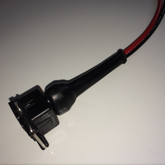
IMG_1689 by MyPix on Talk Photography
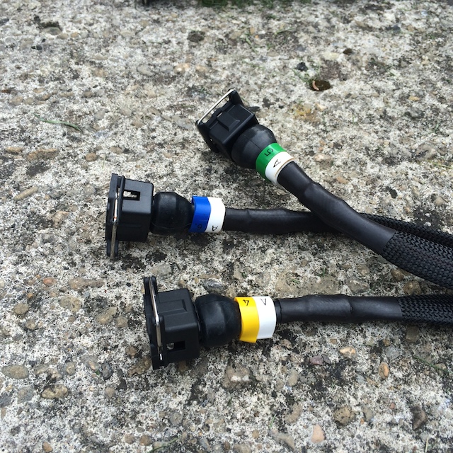
This was done for all four main runs , then i made up the eight plugs with six inch tails, these will be soldered onto the main runs when i am motivated.........
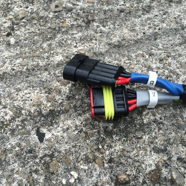
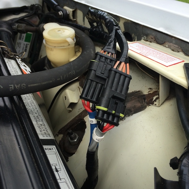
i am wiring the loom as two separate systems, and the heat shrink and heat resistant cable sleeve will be added as i make up the looms , the main 8 pin plug is usually spliced onto these new looms, but i'm going a step further and replacing with modern sealed plugs , one for each bank , male and female , the female will be connected to the main wiring harness on the wing
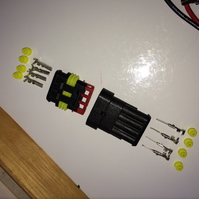
IMG_1695 by MyPix on Talk Photography
when the engine is up to running temperature, i am getting ' some ' rough running, i am putting this down to the old injector loom being crusty , and i do have some broken plug connectors that are not fully secure, and i have already spliced salvaged plugs onto the loom in the past already , so its time for this upgrade
BB
this entailed getting the correct Bosch injector plugs, some heat resistant wiring, some cable sleeving and heat shrink and i also opted for some new 4 pin plugs to replace the original moulded 8 pin Lucas plug behind the offside headlight..
the cable is 16awg 200�C 600v , silicone , the only place i could get it was from Hong Kong by the mtr........ and you need 15mtrs of red and 15mtrs of black , more colours would make it better for identification , but is not really necessary.
so , i now have all the parts , and i decided to start the project today ,
below are the plug components in order of assembly
[/URL]IMG_1688 by MyPix on Talk Photography
next is to measure out the runs ,
there are twelve injectors , with four firing circuits , long runs to A6 and A5 run back to the 8 pin connector , and also runs from B6 and B5 back to the 8 pin connector, the rest of the injectors splice into these looms with three injectors on each one ,
so , A6 , A4 and A2 , with A5 , A3 and A1 on the A bank ,
B6 , B4 and B2 with B5 , B3 and B1 on the B bank
schematic taken from Bernard Embdens site
schematic3 by MyPix on Talk Photography
onto assembly
get a pair of wires measured from B6 to the 8 pin plug , and push over the boot , and the pair of connector seals ,
IMG_1690 by MyPix on Talk Photography
then strip the ends of the wires by about 3mm
IMG_1691 by MyPix on Talk Photography
then crimp on the pair of terminals, i decided not to solder as these are designed to hold perfectly well with just crimping , a standard automotive crimping tool can do this ,
IMG_1692 by MyPix on Talk Photography
then push on the plug so the terminal clicks into place, they will only insert in the correct orientation , so idiot proof ( i hope )
IMG_1694 by MyPix on Talk Photography
once the seals have been pushed home the boot can be pushed over the plug, i quickly found that by pushing the seal towards the terminal, the seal push in most of the way when inserting into the plug
IMG_1689 by MyPix on Talk Photography
This was done for all four main runs , then i made up the eight plugs with six inch tails, these will be soldered onto the main runs when i am motivated.........
i am wiring the loom as two separate systems, and the heat shrink and heat resistant cable sleeve will be added as i make up the looms , the main 8 pin plug is usually spliced onto these new looms, but i'm going a step further and replacing with modern sealed plugs , one for each bank , male and female , the female will be connected to the main wiring harness on the wing
IMG_1695 by MyPix on Talk Photography
when the engine is up to running temperature, i am getting ' some ' rough running, i am putting this down to the old injector loom being crusty , and i do have some broken plug connectors that are not fully secure, and i have already spliced salvaged plugs onto the loom in the past already , so its time for this upgrade
BB
Last edited by Brake buster; Sep 29, 2014 at 10:45 AM.
Thread Starter
|
Senior Member
Joined: Mar 2008
Posts: 821
Likes: 502
From: Gloucester UK
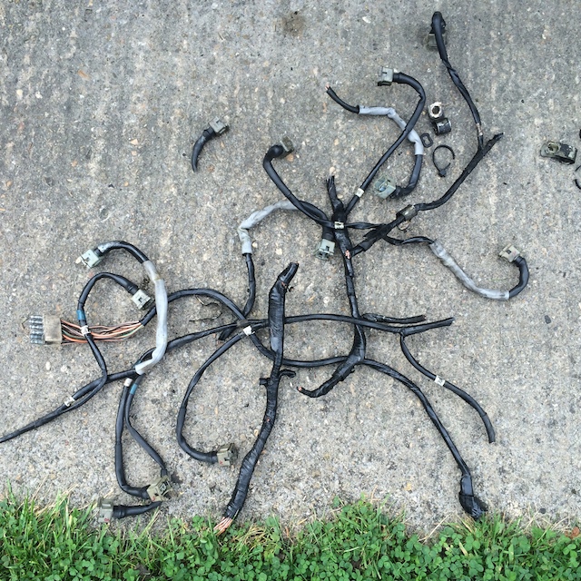
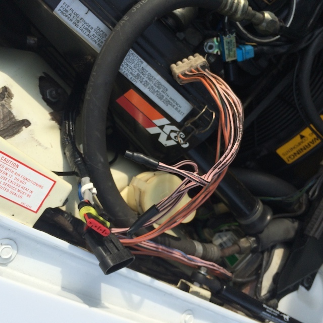
this is what was left of my old injector loom :shock:
no going back now.....
the grey heat shrink indicates where i had spliced in new plugs in the past, but the wire was very crusty where is was against the engine , and most of the plugs were broken
IMG_1937 by MyPix on Talk Photography
SO I MADE THIS :mrgreen:
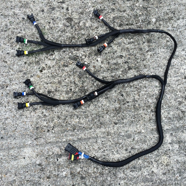
IMG_1933 by MyPix on Talk Photography
when you have two similar plugs located together , its a good tip to alternate the male and female plugs, so when its removed, there is zero guess work as the what goes where
IMG_1934 by MyPix on Talk Photography
IMG_1935 by MyPix on Talk Photography
and the new loom all routed and plugged into the injectors
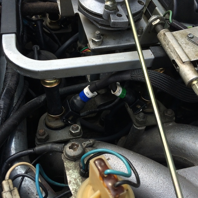
IMG_1940 by MyPix on Talk Photography
then i had to mess with this lot , lol
IMG_1941 by MyPix on Talk Photography
and it turned into this....
IMG_1942 by MyPix on Talk Photography
this is where the self doubt comes in ( yes i do get it , lol ) and i start asking if i have done everything right , ah well , lets turn the key and see, and Phew , first turn of the key and she fires, and it even sounds like all 12 are running , lol

IMG_1944 by MyPix on Talk Photography
i also changed the routing of the main loom, and took it away from the front of the engine, and took it to the right side and under the air box , as there is lots of room there, and i think it looks less cluttered that way ??
this was a very tricky project, and i would , if i had the chance buy a new loom for anything unto �250 if i found one, as the parts and labour for this would come to about the same if it was all added up , the cable and plugs alone, plus heat shrink and sleeving came in around �150 !!
and
i would also make it slightly differently , though mine is OK, it a Mk1 effort, and i could be more generous with the tails for the injectors, as the length disappears once the heat shrink goes on , but they all reached in the end
onto the next project
BB 8)
no going back now.....
the grey heat shrink indicates where i had spliced in new plugs in the past, but the wire was very crusty where is was against the engine , and most of the plugs were broken
IMG_1937 by MyPix on Talk Photography
SO I MADE THIS :mrgreen:
IMG_1933 by MyPix on Talk Photography
when you have two similar plugs located together , its a good tip to alternate the male and female plugs, so when its removed, there is zero guess work as the what goes where
IMG_1934 by MyPix on Talk Photography
IMG_1935 by MyPix on Talk Photography
and the new loom all routed and plugged into the injectors
IMG_1940 by MyPix on Talk Photography
then i had to mess with this lot , lol
IMG_1941 by MyPix on Talk Photography
and it turned into this....
IMG_1942 by MyPix on Talk Photography
this is where the self doubt comes in ( yes i do get it , lol ) and i start asking if i have done everything right , ah well , lets turn the key and see, and Phew , first turn of the key and she fires, and it even sounds like all 12 are running , lol
IMG_1944 by MyPix on Talk Photography
i also changed the routing of the main loom, and took it away from the front of the engine, and took it to the right side and under the air box , as there is lots of room there, and i think it looks less cluttered that way ??
this was a very tricky project, and i would , if i had the chance buy a new loom for anything unto �250 if i found one, as the parts and labour for this would come to about the same if it was all added up , the cable and plugs alone, plus heat shrink and sleeving came in around �150 !!
and
i would also make it slightly differently , though mine is OK, it a Mk1 effort, and i could be more generous with the tails for the injectors, as the length disappears once the heat shrink goes on , but they all reached in the end
onto the next project
BB 8)


Senior Member
Joined: Apr 2013
Posts: 230
Likes: 66
From: Greenville, SC
Looks Awesome!! This is one of the rite of passage projects all V12 XJS owners have to do. What is the name of the 4 wire plugs you used? Yours is the best one I have seen to date. Any recommendations on the bosch injector plugs? I like the ones you used, as all I have seen are ones with the pigtails attached which require a splice (I don't like that).
Trending Topics
Senior Member
Joined: Feb 2014
Posts: 147
Likes: 8
From: USA
A spectacular job! I am in the process of preparing to make a harness for a 95. Unfortunately, the 95 harness not only has 2 looms going up the Vee to the injectors but also another 2 going to the the injector modules on one side and the air and oil temp switches on the other (and everything in between). Its a really journey of discovery and this serves as inspiration. Thanks!
What do you call those natty colored label rings you have installed and where can you get them?
What do you call those natty colored label rings you have installed and where can you get them?
Last edited by macudc; Sep 29, 2014 at 07:26 PM.
Thread Starter
|
Senior Member
Joined: Mar 2008
Posts: 821
Likes: 502
From: Gloucester UK
A spectacular job! I am in the process of preparing to make a harness for a 95. Unfortunately, the 95 harness not only has 2 looms going up the Vee to the injectors but also another 2 going to the the injector modules on one side and the air and oil temp switches on the other (and everything in between). Its a really journey of discovery and this serves as inspiration. Thanks!
What do you call those natty colored label rings you have installed and where can you get them?
What do you call those natty colored label rings you have installed and where can you get them?
' cable markers ' numeric and alphabetic , trouble is , i had to buy a box of each , A , B , 1-6 , but there are 250 in each box, lol so i have a few spare.........
but was thinking of building a few for fellow V12 owners , and now i have a spare original loom end i can do a loom like mine, or with an original end on an exchange basis
BB
Veteran Member
Joined: May 2014
Posts: 5,906
Likes: 2,183
From: Bremen, Germany
I've started work on mine and it will basically look the same, though I plan on doing a few alternations regarding how it shall run from injectors to plug (my plan is to run over to the rear, over the brace bar to the front to avoud it being mounted to the hot water pipes).
Otherwise nice job. Though the plugs arent actually right. They should be AMP juniors... Not the Bosch EV1
Otherwise nice job. Though the plugs arent actually right. They should be AMP juniors... Not the Bosch EV1

Member
Joined: Jan 2014
Posts: 96
Likes: 37
From: Grass Valley ca
Im gathering the parts for this job and have a couple questions.
What size cable sleeve did you use?
How much did you need?
Love the injector connectors,but cant seem to find them on Fleabay.
I have the silicone wire comming, as well as the 4 plug connectors. Have heat shrink tube.
High heat cable sleeve, injector connectors, anything else?
I may hit you up on some of your markers, hate to have to buy 250! Lol!
Thanks,
Pete
Senior Member
Joined: Sep 2014
Posts: 366
Likes: 78
From: Dallas, TX
Thanks for the pics, it looks great and must be on every V12 owners todo list. +1 on the request for some part numbers and suppliers. Fleabay is kinda hard to narrow down without clicking thru all the search results
Thread Starter
|
Senior Member
Joined: Mar 2008
Posts: 821
Likes: 502
From: Gloucester UK
sorry for the delay boys
the sleeve is 1/2" in diameter, but will reduce is slightly stretched, or expand if slightly ' pushed up ' together
i used about six foot of it
the connectors are here , but its a UK source
4 x TUG LOCK Fuel injector plugs with boots Bosch EV1 2 pin Mini Timer Cosworth | eBay
BB
the sleeve is 1/2" in diameter, but will reduce is slightly stretched, or expand if slightly ' pushed up ' together
i used about six foot of it
the connectors are here , but its a UK source
4 x TUG LOCK Fuel injector plugs with boots Bosch EV1 2 pin Mini Timer Cosworth | eBay
BB
Veteran Member
Joined: Aug 2014
Posts: 1,858
Likes: 366
From: Pensacola Florida USA
oh well, I am going to do mine using 6 of those 4 way connectors...
that way I only have to make the loom once,
my loom will be for sequential injection and 2, 3 coil pack ignition... no distb.
but will have connectors that convert that to use the current ECU system.
I just drew it out on paper by hand... will draw it on the computer in a bit (no pun intended)
that way I only have to make the loom once,
my loom will be for sequential injection and 2, 3 coil pack ignition... no distb.
but will have connectors that convert that to use the current ECU system.
I just drew it out on paper by hand... will draw it on the computer in a bit (no pun intended)
Last edited by Jonathan-W; Nov 17, 2014 at 02:44 PM. Reason: spelling

Member
Joined: Oct 2014
Posts: 39
Likes: 3
From: Northwest Arkansas
I'll be really interested to see your ideas on this. I have everything torn down on my 92.5 right now and am going back and forth on how to go.
Senior Member
Joined: Jun 2010
Posts: 535
Likes: 198
From: Napa Ca, United States
Amazing results! I hope my attempt looks half as good as yours! You said you found the supplier for the wire in China? Do you have a link or contact info? Scoured the internet for over an hour and I can't find it!
Thread Starter
|
Senior Member
Joined: Mar 2008
Posts: 821
Likes: 502
From: Gloucester UK
I got the wire from here
10M Red Black 16 AWG Soft Silicon Wire 600V 200�c 3135 | eBay
I bought multiples so I had enough to complete the project with a little spare left over
BB
10M Red Black 16 AWG Soft Silicon Wire 600V 200�c 3135 | eBay
I bought multiples so I had enough to complete the project with a little spare left over
BB