
Please help me identify these SLM resistors!


Thread Starter
|
Senior Member


Joined: Oct 2013
Posts: 735
Likes: 286
From: Las Vegas, NV, USA
Hey Lads,
I broke this out of my original thread in hopes that someone can help me with this specific question.
I have identified the issue with my tail lights due to 2 blown resistors in my SLM. The problem is that the markings are completely gone and I need to pick up replacements.
One post I saw thought these might be high-temp 1ohm resistors, 5watt at 5% but there was no follow up to confirm whether or not they worked. Does anyone have an SLM that they could open up and put a number against these two resistors?
They are R79 and R92 on the SLM, PCB

Veteran Member

Joined: Apr 2014
Posts: 4,812
Likes: 3,025
From: Jersey, Channel Islands
Hi Razorboy,
Nice fry-up
If someone chimes in with either a picture or the values then it could be an easy fix.You haven't mentioned any warning messages so the sensing circuitry around the burnt parts may well have survived.
If nobody has one on the bench, then it's possible to work out what the values should be. You are not far off with 1 ohm: could be anywhere between about .3 to 1.5 ohms. They need to be 5W rating, and preferably wire wound.
We need to determine which lamps the two resistors are in circuit with. Firstly, which lamps are still not working. You mentioned before that one brake light was out - is this now OK and it's just the tail lamps?
Are you're comfortable with a multimeter?
Mike
Thread Starter
|
Senior Member
Joined: Oct 2013
Posts: 735
Likes: 286
From: Las Vegas, NV, USA
Hi Razorboy,
Nice fry-up
If someone chimes in with either a picture or the values then it could be an easy fix.You haven't mentioned any warning messages so the sensing circuitry around the burnt parts may well have survived.
If nobody has one on the bench, then it's possible to work out what the values should be. You are not far off with 1 ohm: could be anywhere between about .3 to 1.5 ohms. They need to be 5W rating, and preferably wire wound.
We need to determine which lamps the two resistors are in circuit with. Firstly, which lamps are still not working. You mentioned before that one brake light was out - is this now OK and it's just the tail lamps?
Are you're comfortable with a multimeter?
Mike
Nice fry-up
If someone chimes in with either a picture or the values then it could be an easy fix.You haven't mentioned any warning messages so the sensing circuitry around the burnt parts may well have survived.
If nobody has one on the bench, then it's possible to work out what the values should be. You are not far off with 1 ohm: could be anywhere between about .3 to 1.5 ohms. They need to be 5W rating, and preferably wire wound.
We need to determine which lamps the two resistors are in circuit with. Firstly, which lamps are still not working. You mentioned before that one brake light was out - is this now OK and it's just the tail lamps?
Are you're comfortable with a multimeter?
Mike
Yes I am good with a meter.
The original problem is still the problem.
No park lights and one brake light missing (P-side)
I was getting a lamp out indication on my dash when I would use my lights so the SLM is responding to that. Problem is that the wiring and subsequent bulb arrangement was so jacked that I just opted to cut the entire rats nest out and start over.
Its pretty clear that these two resistors are shot.
I have removed them already from the PCB and then checked the traces that they were associated with as the PCB is a little charred around that area. The traces have come up good. Still passing signal and little to no resistance on the circuit.
My hope, of course is that these two resistors are responsible for the lamps not functioning.
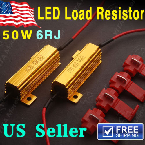
In the other thread I found there was a suggestion for this resistor:
AC05000001008JAC00 Vishay BC Components | Resistors | DigiKey
Does it look like it would get the job done?
Thanks for helping
Thread Starter
|
Senior Member
Joined: Oct 2013
Posts: 735
Likes: 286
From: Las Vegas, NV, USA
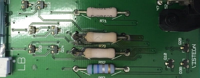
Here is the thread I found regarding the resistors.
Looks like this area can be a problem child.
https://www.jaguarforums.com/forum/x...values-132499/
Looks like this area can be a problem child.
https://www.jaguarforums.com/forum/x...values-132499/
Veteran Member
Joined: Apr 2014
Posts: 4,812
Likes: 3,025
From: Jersey, Channel Islands
Hi Bernie,
That picture was a really good find. You've done a better job with your searches than I did..
I can now see what I expected: 3 pairs of resistors. R79 is clearly 1 ohm, so WhiteXKR's suggestion is good for you too. It is a standard value so will be easy to source.
R92 is going to be the same as R79 at 1 ohm. One for each tail lamp.
As you're intending to use LEDs, you have a bit of latitude upwards in value, but I'd recommend staying with the correct values in case you ever revert to normal incandescent lamps.
It may be the angle of the shots, but all six look to be mounted tight to the circuit board, which is not particularly good practice. When you put the replacements in, leave the legs a little longer so there's a gap between the resistor body and the circuit board if there's room in there.
That leaves the one missing brake lamp. Once you've replaced the fries, check for 12v on B42-1 (RH) and B42-2 (LH) when the brake pedal is pressed. If there's voltage present on both, then it's the wiring from the SLCM to the cluster that's the culprit. If not, report back.
Do expect bulb fail messages from using LEDs, but you'll be a lot closer.
Sorry it's a bit long-winded, but my car has the older SLCM where this circuitry is split out into a separate module, so I can't dive out and check. The principle is the same, but the values aren't.
Mike
Last edited by michaelh; Mar 31, 2016 at 01:39 PM.
Thread Starter
|
Senior Member
Joined: Oct 2013
Posts: 735
Likes: 286
From: Las Vegas, NV, USA
Thank you sir!
Ok, let me review this with you so you know the whole story.....lol.
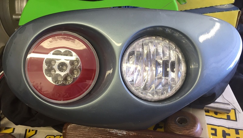
The car came with aftermarket tail lights and the primary red lenses were completely destroyed. The lenses were bubbled on the front and completely melted on the rear. The clear inside lenses were ok.
The way they hold these lenses into the molded frames is laughable. They are simply held in with an silicone adhesive. There is no real way out of that now and I am going to end up doing the same thing.
Ok, first I went to ebay to see if I could find an original pair of jewel tail assemblies for the car. The prices for them are up there from 150-200 a piece so I decided to not go that route and to try and save the original lenses. I measured it out and managed to find a set of aftermarket LED complete assemblies that with some cutting and shaping, fit into the original holes.
Now I do have a small issue.
The lenses only have 2 conductors plus ground. One lights up the outer ring and the other lights up the inner portion and the outer ring. Its a 3-wire assembly. So that means at most I can only have park and one other on these lenses ( I am assuming right now brake)
The clear lenses had a 1157 bulb in there, probably for backup and fog in the rear? Dunno, never checked. I have an option here to install a bi-color LED bulb in the clear lenses which provides backup and indicator. They have them on ebay amber / white.
The entire arrangement will be LED when I am done so I was assuming I would need to put some resistors in the circuit to fool the SLM into thinking that it was bulbs instead. Thoughts?
One bummer on this project and it was a big one.
The LED assemblies only cost me 27.00 for the pair so I originally thought I had totally scored. Upon cutting out the old silicone adhesive and removing the old lense, the paint lifted and pulled off the part on both sides - couldn't stop it - shitty paintjob. I am taking them to my local Maaco who will do them for me with premium prep and paint but its going to cost me 150.00. Yeesh. By the time I am done, I would have the original jewel lenses paid for lol.
Ok, let me review this with you so you know the whole story.....lol.
The car came with aftermarket tail lights and the primary red lenses were completely destroyed. The lenses were bubbled on the front and completely melted on the rear. The clear inside lenses were ok.
The way they hold these lenses into the molded frames is laughable. They are simply held in with an silicone adhesive. There is no real way out of that now and I am going to end up doing the same thing.
Ok, first I went to ebay to see if I could find an original pair of jewel tail assemblies for the car. The prices for them are up there from 150-200 a piece so I decided to not go that route and to try and save the original lenses. I measured it out and managed to find a set of aftermarket LED complete assemblies that with some cutting and shaping, fit into the original holes.

Now I do have a small issue.
The lenses only have 2 conductors plus ground. One lights up the outer ring and the other lights up the inner portion and the outer ring. Its a 3-wire assembly. So that means at most I can only have park and one other on these lenses ( I am assuming right now brake)
The clear lenses had a 1157 bulb in there, probably for backup and fog in the rear? Dunno, never checked. I have an option here to install a bi-color LED bulb in the clear lenses which provides backup and indicator. They have them on ebay amber / white.
The entire arrangement will be LED when I am done so I was assuming I would need to put some resistors in the circuit to fool the SLM into thinking that it was bulbs instead. Thoughts?

One bummer on this project and it was a big one.
The LED assemblies only cost me 27.00 for the pair so I originally thought I had totally scored. Upon cutting out the old silicone adhesive and removing the old lense, the paint lifted and pulled off the part on both sides - couldn't stop it - shitty paintjob. I am taking them to my local Maaco who will do them for me with premium prep and paint but its going to cost me 150.00. Yeesh. By the time I am done, I would have the original jewel lenses paid for lol.
Veteran Member
Joined: Apr 2014
Posts: 4,812
Likes: 3,025
From: Jersey, Channel Islands
Shame about the paint - what a PITA. RTV and hot glue are not silver bullets!
If the old lenses were melted then someone may have fitted the wrong bulbs in there which could have caused the damage to the SLCM.
I guess you're sacrificing the fog lamps: that's OK as there's no fail sensing on them.
Neat idea about the combined indicator/reversing lamps. You'll need to load the indicators else the BPM will sense the reduced load and start flashing them at double? speed. Reversing lamps are fed from the SLCM but I doubt if they're monitored.
I see that the tail lights are twinned up from 2001, so a 12 ohm load should fool the sensors. The ones you've pictured will be fine for both the brake and indicators.
How things go in circles.. Jaguar built in monitoring for the lamps we can't easily check while driving, then LEDs come along which are more efficient and (theoretically at least) reliable. We then have to defeat those same protections in order to use them
One advantage of the old arrangement is that it's very easy to turn all the monitoring off. I imagine it is possible in the newer SLCM too, with a little reverse-engineering.
Please post some pics once you get it all back together.
Best,
Mike
PS I'll put those resistor values into a post so they may help someone in the same situation.
Trending Topics
Thread Starter
|
Senior Member
Joined: Oct 2013
Posts: 735
Likes: 286
From: Las Vegas, NV, USA
I went ahead and ordered the resistors from DigiKey.
Should have them beginning of the week and we will see what effect it has on my tail lights.
The amber/white LED's I have been seeing are all called "Switchback" LED's. The original purpose is for front markers whereby the lights are white until you use the indicator and then they turn to amber and then back to white again once the indicator is turned off. Not sure if this is something that is being done inside the bulb or if it is just describing the application?
It's on a 2 conductor socket like a 1157 so I assume that each group of LED's gets its own signal which is what I need. If there is some convoluted PCB in there that does something else, I am going to have to look around.
What I do fear right now is getting a bright enough bulb to do the job. There are so many choices for these starting at 5-6 bucks and going up to 35-40 a piece. Probably all made in China anyway. I am learning the differences in the technology and what is the most up to date. Some point to the Lumens their product has which is a big help while most don't.
Right now, I am looking into 120 versions of the bulb

Thread
Thread Starter
Forum
Replies
Last Post
Ron_C
XF and XFR ( X250 )
10
Mar 5, 2016 06:26 AM
Currently Active Users Viewing This Thread: 1 (0 members and 1 guests)