When you click on links to various merchants on this site and make a purchase, this can result in this site earning a commission. Affiliate programs and affiliations include, but are not limited to, the eBay Partner Network.
Relocating side repeaters to the bumper parking lights?
Some months ago, I came across a post where a user mentioned relocating the side repeater function from the amber wing lights to the amber front bumper parking lights (which means you can put the much better-looking leaper badges on the wings instead of the ambers without sacrificing having a turn-signal visible from the side). It was mentioned in the context of not being as straight-forward as it may seem, and I think maybe a wiring diagram was offered. I apparently didn't bookmark it, and now I can't find it. I've searched extensively but don't remember the parent thread, nor the user posting it, so no luck.
Anybody able to help?
Thanks!
Thanks guys!
Although, that actually wasn't the thread I recalled.
I believe the reason complexity was mentioned was because in the US, the side marker serve as parking lights/side marker lights, which I understand we have to have. By relocating the repeater to it, it would have to do triple-duty: parking light, turn signal, and emergency flashing. Hence, the need for a bit of circuitry rather than just rerouting the wiring.
Regarding what's required: the requirements for turn signal lights are written with a degree of ambiguity that leaves room for interpretation, at least in my adopted home state of Pennsylvania. However, I have seen several XK8/R that have leaper badges on the wings instead of repeaters, so it's apparently at least tolerated.
Side note: there is on-going debate among the PA politicians whether to get rid of the annual safety inspections, just like our neighbor state OH. If that happens, I suppose we'll get away with just about anything.
Having tried various electronic ways to switch the side marker bulb OFF and back ON to make if flash I came to the conclusion you need a change over relay where the bulb when ON continuously gets it +ve feed via the NC contacts and when activated by a feed from the indicators the relay turns off the bulb . hence it flashes with the standard indicators.
Last edited by Pistnbroke; Apr 21, 2025 at 01:37 AM.
Having tried various electronic ways to switch the side marker bulb OFF and back ON to make if flash I came to the conclusion you need a change over relay where the bulb when ON continuously gets it +ve feed via the NC contacts and when activated by a feed from the indicators the relay turns off the bulb . hence it flashes with the standard indicators.
That seems like a good way to do it, although I think it will only work with the rotary knob in positions 2,3 and 4 since the side markers are OFF in position 1. I guess a second relay could be added to give the bulbs +ve from the indicator signal when they are nominally OFF? Probably also needs a few diodes here and there to avoid back-feeding. I'm not smart enough to visualize what the circuitry would look like in my head, will try to draw it up once I'm off work today. Fun challenge!
Thanks!
Ok, I think something like this should work, two NC relays and two diodes per side.
Once I get around to doing this, I will most likely tap into the wing repeater wiring instead of the headlight harness (less likely to screw something up).
In knob positions 2-3-4, the flashing will be out of sync of the headlight flashing, but I don't think that's a problem(?)
I think your circuit will work as you expect. Make sure you use relays with flyback protection - i.e. a diode or resistor across the coils.
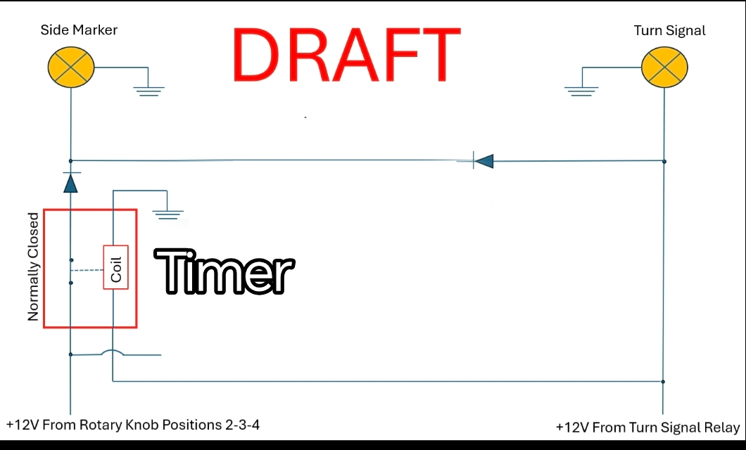
If I was doing it, I would replace the left hand relay with a timer module and get rid of the right hand relay so the diode is always connected to the side marker. The idea would be that the headlights switch would power the side marker normally, but when the direction indicators are on, the timer would open that NC relay and the indicator would then be flashing the side light. That way the side marker would flash in time with the indicators rather than out of phase. Something like this (I haven't checked if this is exactly the right one):-
I think your circuit will work as you expect. Make sure you use relays with flyback protection - i.e. a diode or resistor across the coils.
If I was doing it, I would replace the left hand relay with a timer module and get rid of the right hand relay so the diode is always connected to the side marker. The idea would be that the headlights switch would power the side marker normally, but when the direction indicators are on, the timer would open that NC relay and the indicator would then be flashing the side light. That way the side marker would flash in time with the indicators rather than out of phase. Something like this (I haven't checked if this is exactly the right one):-
Thanks for the feedback!
That'd be a great solution to the out-of-sync but I don't see that this relay by itself can be wired to enable the indicator to flash unless the side markers were in an ON position? That's the reason I toyed with including a second relay, to have the indicator enabled regardless of headlight switch position.
I'm not finding many relays that explicitly list having diodes for flyback protection, is that because most have it and don't show it, or because it's uncommon?
This looks like it will fit the bill
I did it this way, putting leapers on the side and moving the flash to the corner. How I did it.
Very nice, thanks for that! The detailed pictures are much appreciated, wish I had the discipline to document my work in the same way.
I'm definitely stealing your idea of using an EV1 male to the existing wing connector rather than splicing to it.
I have to ponder a bit if I want to add a bulb to the housing like you did, or stay with the original plan to have the existing bulb do it all through relays. I'm a bit reluctant to drill into the housing, the old plastics issue...
The side marker is powered by the indicators when flashing, or by the headlights when they are on. The timer disconnects the headlight feed when the indicators are flashing.
That relay you linked to looks like it has suitable flyback protection - I would test it with a multimeter to be sure.